Projects
.jpg) Solutions
Solutions Services
 News
News About Us


-
Product Overview
-
Product Details
-
Data Download
-
Related Products
")
")
")
")
")
")
")
")
")
")
YSM6-12~24 Air-insulated RMU(Fixed Type)
YSM6-12/24 unit type SF6 RMU with SF6 load switch as main switch,for whole cabinet issuitable forelectric distributionautomation and compact alsoexpandable metal close switchgeart Itcharacters in its simplestructure,flexible operation,reliableinterlocking andconvenient installation etc,which can provide the satisfactory technical projects both for different applicationoccasions and users.Withthe adoption of sensor technology and the protection relay up to date,plus the advanced technologyand flexible assemblyproject.
Contact Us
Product Details
YSM6-12/24 unit type SF6 RMU with SF6 load switch as main switch, for whole cabinet is suitable for electric distribution automation and compact also expandable metal close switchgear. It characters in its simple structure, flexible operation, reliable interlocking and convenient installation etc., which can provide the satisfactory technical projects both for different application occasions and users. With the adoption of sensor technology and the protection relay up to date, plus the advanced technology and flexible assembly project.
C YSM6-12/24 unit type SF6 RMU can completely meet the requirement of continuously variable market. It can take self-produced SF6- 12/24 load break switch; Operational methods for the main switch inside ring main unit can be either manual or electric power driven. And it can meet the requirement of "Four Controls" when matched with FTU and RTU.
Selection

Operating conditions
1. Air temperature: Maximum temperature: +40℃; Minimum temperature:-5℃
2. Humidity: Monthly average humidity 95%; Daily average humidity 90% .
3. Altitude above sea level: Maximum installation altitude: 2000m
4. Ambient air not apparently polluted by corrosive and flammable gas, vapor etc.
5. No frequent violent shake
Features
1. Incoming unit with switch disconnector(Load break switch) schemas With other extra components optional Outgoing unit with
2. Fuse-switch protection schemas
3. With other extra components optional Incoming/outgoing circuit breaker protection schemas With other extra components
4. optional MV metering schemas
5. With other extra components optional Casings (Bus bar Panel) schemasWith other extra components optional
6. Others
Technical data
| NO. | Items | Unit | Parameter | |
| 1 | Rated voltage | kV | 12 | 24 |
| 2 | Rated frequency | Hz | 50/60 | |
| 3 | Rated current | A | 630/800 | |
| 4 | 1min Power frequency withstand voltage | kV | 48 | 60 |
| 5 | Lightning impulse withstand voltage | kV | 75 | 125/150 |
| 6 | Rated short circuit breaking current (peak) | kA | 80 | 63 |
| 7 | Rated active load/close circuit breaking current | A | 63 | 50 |
| 8 | Rated transferring current | A | 1700 | 1200 |
| 9 | Rated short circuit making current (peak) | kA | 80 | 63 |
| 10 | Rated cable(line) charging breaking current | A | 50 and 10 | |
| 11 | Cable charge breaking current in earthing fault | A | 20 | 20 |
| 12 | Rated withstand current (peak) | kA | 80 | 63 |
| 13 | Short time withstand current (2s) | kA | 31.5 | 25 |
| 14 | Mechanism life | times | 2000 | |
Note: For short circuit breaking and peak current is based on Fuse plus combination.
For distribution switchboard schema
1. Switch disconnector

2. Fuse-switch protection

3. Circuit-breaker protection

4. MV metering

5. Casings (Bus bar Panel)

2. Fuse-switch protection

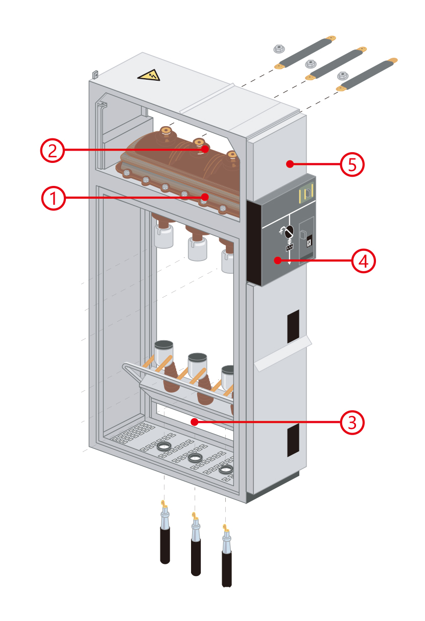
5 parts for the unit type SF6 ring main unit:
1. switch cubicle switch-disconnector and earthing switch in an enclosure filled with SF6 and satisfying “sealed pressure system ” requirements.
2. bus-bar cubicle all in the same horizontal plane, thus enabling later switchboard extensions and connection to existing equipment.
3. connection cubicle accessible through front, connection to the lower switch- disconnector and earthing switch terminals (IM cubicles) or the lower fuse- holders ( PM and QM cubicles). This compartment is also equipped with an
earthing switch downstream from the MV fuses for the protection units.
4. operation mechanism, interlocking contains the elements used to operate the switchdisconnector and earthing switch and actuate the corresponding
indications (positive break).
5. Low voltage cubicle (upper & lower enclosure structure) installation of a
terminal block (if motor option installed), LV fuses and compact relay devices. If more space is required, an additional enclosure may be added on top of the
cubicle.
6. Optional switch cubicles (IM) can also be fitted with: control motorisation;
surge arrestors.
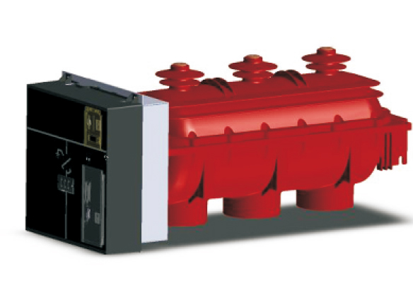
The three-phase rotary contact is installed in a gas chamber filled with SF6 gas and the relative pressure is 0.4bars. It has excellent operation performance with safety and reliability.
● Tightness:
The air chamber is filled with SF6 gas, which meets the standard requirements of "closed pressure system ", and the sealing performance has been checked and
inspected in the factory.
● Operational Safety:
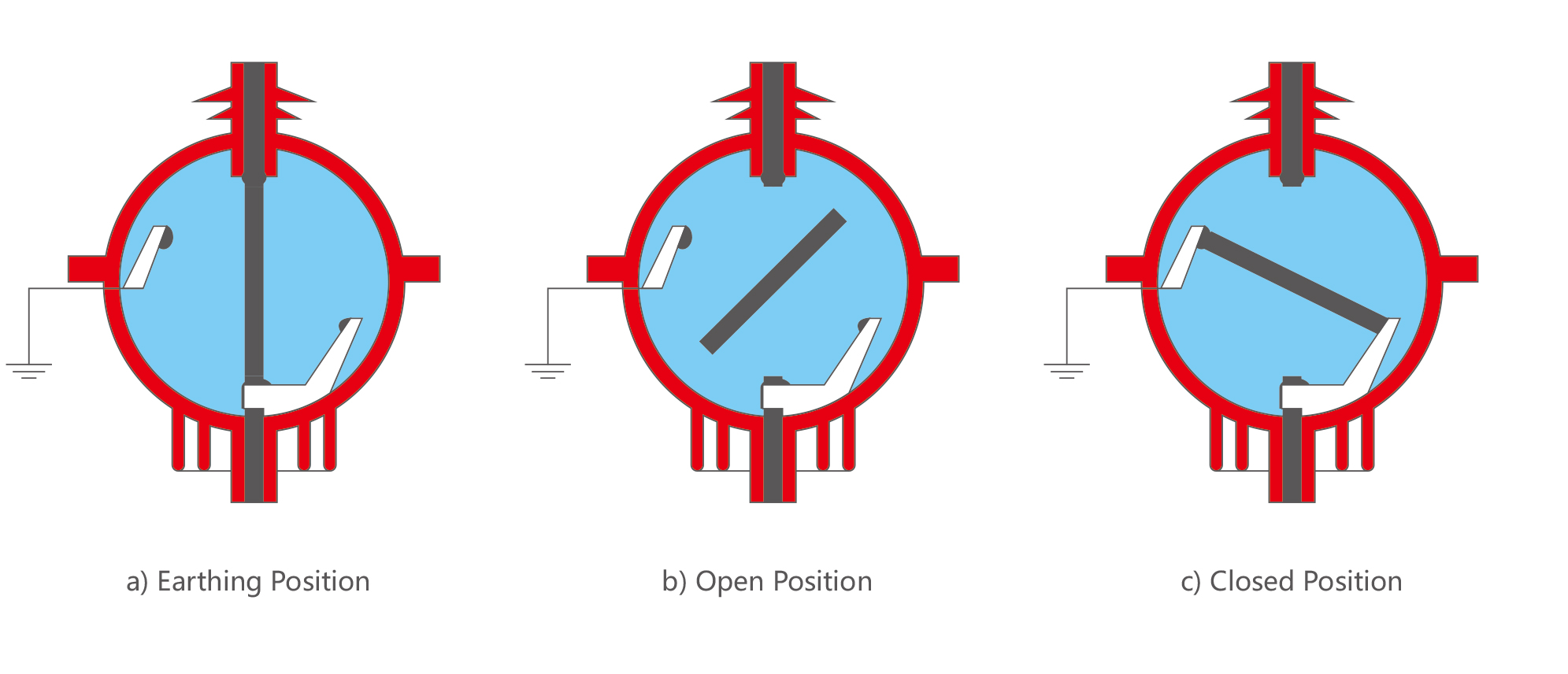
1. The switch has three positions of "closed ", "open" and "grounded ", and has a
locking function to prevent accidental operation. The contact is driven to rotate by
the spring energy storage mechanism, which is not affected by human operation factors.
2. Has "break " and isolation functions.
3. The short-circuit making capacity of the SF6 grounding switch meets the standard requirements.
4. In the event of an accident, the pressure drops after the overpressured SF6 gas breaks through the safety diaphragm, and the gas will directly be sprayed into the back of the cabinet for safety.
Breaking Principle:
SF6 gas has excellent arc extinguishing performance. When the switch is opened, the relative movement between the arc and the gas will extinguish the arc. When the moving and static contacts are separated, the arc appears in the electromagnetic field generated by the permanent magnet, and the arc is
elongated and extinguished when the current crosses zero by SF6 gas. The distance between the moving and static contacts is sufficient to withstand the recovery overvoltage. The system is simple and reliable, with minimal contact wear and long electrical life.
● Switchgear status indicator:
Fitted directly to the drive shaft, these give a defi nite indication of the contact ’s position. (appendix A of standard IEC 62271-102).
● Operating lever:
This is designed with an anti-refl ex device that stops any attempt to reopen the device immediately after closing the switch or the earthing disconnector.
● Locking device:
Between one and three padlocks enable the following to be locked:
● access to the switching shaft of the switch or the circuit breaker
● access to the switching shaft of the earthing disconnector
● operating of the opening release push-button. ●Simple and effortless switching
Mechanical and electrical controls are side by side on the front fascia,on a panel
including the schematic diagram indicating the device ’s status (closed, open, earthed):
● Closed:
the drive shaft is operated via a quick acting mechanism,independent of the operator. No energy is stored in the switch, apart from when switching
operations are taking place.
For combined switch fuses, the opening mechanism is armed at the same time as the contacts are closed.
● Opening:
the switch is opened using the same quick acting mechanism,operated in the opposite direction.
For a combined switch fuses unit, opening is controlled by:
● a push-button
● a fault.
● Earthing:
a specifi c control shaft enables the opening or closing of the earthing contacts. Access to this shaft is blocked by a cover that can be slid back if the switch is
open but which remains locked in place if it is closed.
Voltage presence indicator
This device has integrated VPIS (Voltage Presence Indicating System) type lights, in conformity with IEC standard 61958, enabling the presence (or absence) of voltage to be checked on the cables.
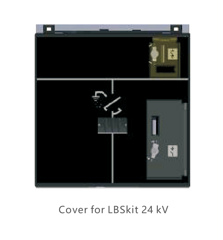
Insensitivity to the environment
● An internal sealed enclosure, contains the active parts of the LBSkit
(switch, earthing disconnector). It is filled with SF6 in accordance with the defi nitions in IEC recommendation 62271-200 for “sealed pressure
systems ”.
Sealing is systematically checked in the factory.
● Parts are designed in order to obtain optimum electrical fi eld distribution.
Overall and mounting dimensions(mm)
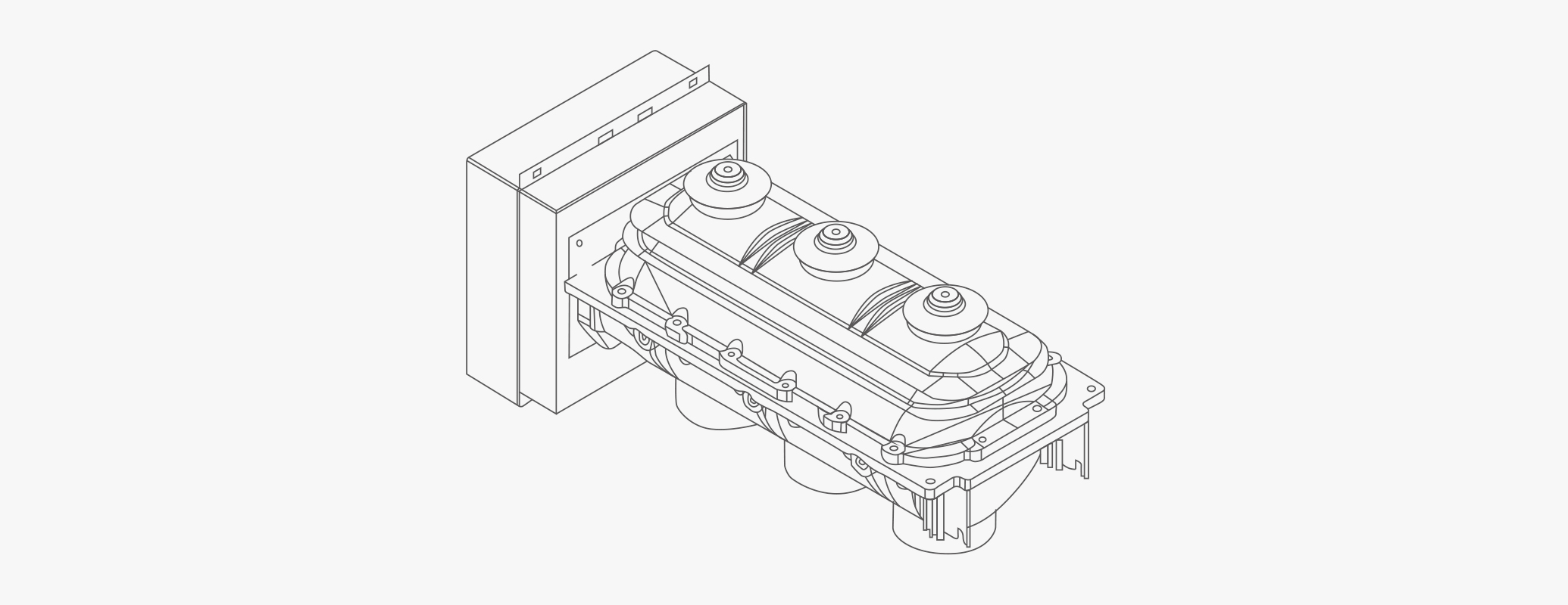
Matching Overall and mounting dimensions(mm) of SF6 load break switch-fuse combination Fig 1) SF6 load break switch without upper cubicle
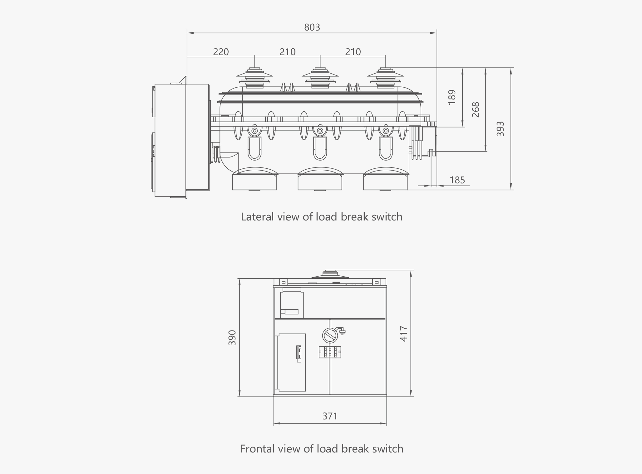
Fig 2) Whole Load break switch outline
Leave Your Message

Related Products
-
-3,6,10(Q) Load Switch") JDZ(J)-3,6,10(Q) Load SwitchZN23-40.5 Indoor Vacuum Circuit Breaker ZN23-40.5 MV vacuum circuit breaker is indoor MV distribution device of three-phase AC 50Hz, rated voltage 40.5kV, can be matched with JYN35/GBC-35 type switch cabinet. Suitable for control and protection in power plant, substation and power distribution system, especially suitable for frequent operation places. The vacuum circuit breaker is handcart type, with reasonable structure, convenient maintenance, safe and reliable use...
JDZ(J)-3,6,10(Q) Load SwitchZN23-40.5 Indoor Vacuum Circuit Breaker ZN23-40.5 MV vacuum circuit breaker is indoor MV distribution device of three-phase AC 50Hz, rated voltage 40.5kV, can be matched with JYN35/GBC-35 type switch cabinet. Suitable for control and protection in power plant, substation and power distribution system, especially suitable for frequent operation places. The vacuum circuit breaker is handcart type, with reasonable structure, convenient maintenance, safe and reliable use... -
 KYN61-40.5 Metalclad AC Enclosed SwitchgearMedium Voltage Switchgear KYN61-40.5 Metalclad AC Enclosed Switchgear, Withdrawable Type KYN61-40.5 Air insulated metal clad movable switchgear is an indoor switchgear,assembly operating under the conditions of 50/60Hz three phase and rated 40.5kV AC voltage,which is applied to the transmission and distribution for generators,transformer substations and the industry and mine enterprises. It also can be used to control,protect and monitor electric circuits,and very us...
 -
 MNS Low Voltage SwitchgearLow Voltage Switchgear MNS Low-voltage Switchgear Panel, Withdrawable Type MNS low-voltage withdrawable switchgear is suitable for power systems with an AC 50Hz and a rated working voltage of 400V. It is mainly used for energy conversion, distribution, and control of distribution equipment. Mainly suitable for airports, power stations, transportation and energy, industrial and mining enterprises, residential communities, and other places. Standard: IEC439 Selection ...
 -
 JN17 Indoor Grounding Switch● JN17-12/40 (old type is JN15-12/40) series indoor MV earthing switch is a new design and improved product of our company according to the ES1 type, the structure is assembled, suitable for electric power system with 3-10KV, Three-phase,AC 50(60)Hz,supported with various kinds of HV switchgear and as earthing protection. ● Standard: IEC 129,IEC 62271-102. Selection Operating conditions 1. Ambient temperature:-10~+40℃ 2. Altitude: ≤1000m (sensor height:140mm) 3. Rel...
 -
 SZ□-35KV Oil-Immersed Transformer.SZ□-35KV Series On-load Voltage Regulating Transformer This kind of product is applied to power system of three-phase, 50Hz as well as 35kV and below,is the main transformer equipment of medium and small-sized transformer substation, supplies power distribution, power and illumination for the industry and agriculture. The company introduces in domestic and overseas advanced technique, adopts the latest material and optimizes design, which enables the product structur...
 -
 XRNT Current-limiting Fuses for Transformer Pro...● lt can be used in indoor system of 50HZ and rated voltage of 3.6KV, 7.2KV, 12KV, 24KV,40.5KV;Used together with other switch facilities such as loading swithes, vacuum contactors,it can protect electric transformers and other electric facilities against overloading or circuit break. It is also a necessary accessory for high-voltage switchbox,circular circuit cabinet,high / Low voltage top-loading transformer substation. Selection Technical data Ty...
-3,6,10(Q) Load Switch")


-

-

-

Address:CNC High-Tech Hutou Industrial Zone, Liushi Town, Yueqing, Wenzhou Ctity, China


Hot Products - Sitemap - AMP Mobile
250amp Mccb Circuit Breaker, 3p Ac Mcb, 6a Elcb, Mccb Microprocessor Based, Mpcb, 3 Phase Starter,