Projects
.jpg) Solutions
Solutions Services
 News
News About Us


-
Product Overview
-
Product Details
-
Data Download
-
Related Products


YRM6 Gas-insulated Metal-enclosed Switchgear
YRM6 fully insulated fully enclosed compact switchgear,which can realize functions of control,protection,measurement.monitoring,communication,etc.is especially suitable for places with small distribution faility site and high reliabilityrequirements,and places with a relatively harsh natural environment and conditions.such as underground,highland and coastalareas.
Contact Us
Product Details
YRM6 fully insulated fully enclosed compact switchgear, which can realize functions of control, protection, measurement, monitoring, communication, etc. is especially suitable for places with small distribution facility site and high reliability requirements, and places with a relatively harsh natural environment and conditions. such as underground, highland and coastal areas.
lt is mainly used in areas where land is tight and space is limited, high reliability is required, like industrial and mining enterprises and substations, subways, light rail railways, etc.
Selection

Operating conditions
1. Ambient air temperature: -40℃~+40℃;
2. Relative air humidity: daily average <95%, monthly average <90%;
3. Altitude ≤1500m (under standard inflation pressure);
4. Seismic intensity <9 class;
5. Places free from fire, explosion, serious contamination, chemical corrosion and severe vibration.
Special conditions
Manufacturers and end users must agree on special Operating conditions that are different from normal operating conditions; lf a particularly harsh operating environment is involved, the manufacturer and supplier must be consulted;
When electrical equipment is installed at an altitude of 1500 meters or more, special instructions are required to adjust the pressure during manufacturing. When the pressure is adjusted, the life of the switchgear itself has no significant effect.
Features
● Modular design
The switch is divided into fixed module and expandable module group. In the same SF6 insulated air chamber, up to6 modules can be configured. Switching cabinets with more than 6 modules must be connected with the expansion busbar to realize the semi-module. Structure, full module configuration can also be achieved by using an extended bus between all modules. Through the combination of different functional modules, a simple to complex power distribution scheme can be formed to meet various configuration requirements in the secondary substation and the opening and closing.
● Compact structure
Except for the air-insulated metering cabinet, all modules are only 325mm wide and the metering cabinet width is 695mm; the cable joints of all units are the same height to the ground, which is convenient for on-site Features.
● Unaffected by the environment
All high-voltage live parts are installed in a sealed stainless steel case. The case is welded with a stainless steel plate and filled with SF6 gas at a working pressure of 1.4 bar. The degree of protection is IP67.It can be used in places where it is installed in damp, dusty, salt spray, mine, box-type substation and air pollution. Even the fuse compartment has an lP67 rating. The extension busbars are completely insulated and shielded to ensure that they are not affected by changes in the external environment.
● Highly reliable personal safety
All live parts are enclosed in the SF6 air chamber, the switch has a reliable pressure relief channel, the load and grounding switches are three-position switches, simplifying the interlocking between each other, reliable mechanical interlock between the cable compartment cover and the load switch .
Performance Index
● SF6 gas pressure: 1.4bar under 20℃ (absolute pressure)
● Annual leakage rate: 0.25%/year
● Protection grade SF6 gas room: IP67 Fuse tube: IP67
● Switchgear enclosure: IP3X
● Busbar
Switchgear internal busbar: 400mm2Cu Switchgear earthing busbar: 150mm2Cu
Thickness of gas room stainless steel enclosure: 3.0mm
● The front panel and the side panel of the switchgear, and the front cover of the cable room, the company's standard color is: jade color 7783; if users have special requirements, please put forward when ordering.
Standard
● High-voltage alternating-current circuit-breakers (IEC 62271-100:2001, MOD)
● High-voltage alternating-current disconnectors and earthing switches (IEC 62271-102:2002,MOD)
● Common specifications for high-voltage switchgear and controlgear standards
● High-voltage alternating-current switches for rated voltage above 3.6kV and less than 40.5kV(IEC60265-1-1998,MOD)
● Alternating-current metal-enclosed switchgear and controlgear for rated voltages above 3.6kV and up to and including 40.5kV (IEC62271-200-2003, MOD)
● Degrees of protection provided by enclosure (IP code) (IEC 60529-2001,IDT)
● High-voltage alternating current switch-fuse combinations (IEC6227-105-2002,MOD)
● DL/T 402 Specification of high-voltage alternating-current circuit-breakers (IEC 62271-100-2001,MOD)
● DLT 403 HV vacuum circuit-breaker for rated voltage 12kv to 40.5kv
● DLT404 Alternating-current metal-enclosed switchgear and controlgear for rated voltages above 3.6kV and up toand including 40.5kV
● DL/T 486 HVAC disconnectors and earthing switches (IEC62271-102-2002,MOD)
● DLT593 Common specifications for high-voltage switchgear and controlgear standards IEC 60694-2002,MOD)
● DLT 728 Technical guide for the order of gas-insulated metal-enclosed switchgear (IEC815-1986, IEC 859-1986)
● DL/T 791 Specification of indoor AC HV gas-filled switchgear panel
Technical data
| NO. | Items | Unit | Value | |||
| Load break switch | Combination | Vacuum circuit breaker | ||||
| 1 | Rated coltage | kV | 12/24 | |||
| 2 | Rated frequency | Hz | 50/60 | |||
| 3 | Power frequency withstand voltage | phase-to-phasel | A | 60 | ≤125 | 630/1250 |
| across open contacts | kV | 42/65 | ||||
| 4 | Lightning impulse withstand voltage | phase-to-phasel | kV | 75/125 | ||
| across open contacts | kV | 85/145 | ||||
| 5 | Rated short time withstand current | KA/4s | 20/20 | / | 20/25 | |
| 6 | Rated peak withstand current | KA | 50/50 | / | 50/63 | |
| 7 | Rated short circuit making current (peak) | KA | 50/50 | 80/80 | 50/63 | |
| 8 | Rated short circuit current | KA | / | 31.5/31.5 | 20/25 | |
| 9 | Rated transfer current | A | / | 1700/1400 | / | |
| 10 | Rated closed-loop breaking current | A | 630/630 | / | / | |
| 11 | Rated cable charging breaking current | A | 10/25 | / | / | |
| 12 | Mechanical life | Times | 5000 | 3000 | 5000 | |
Note 1: depends on the rated current of fuse.
Standard modules
Each module of the YRM6 type switchgear has the following configurations:
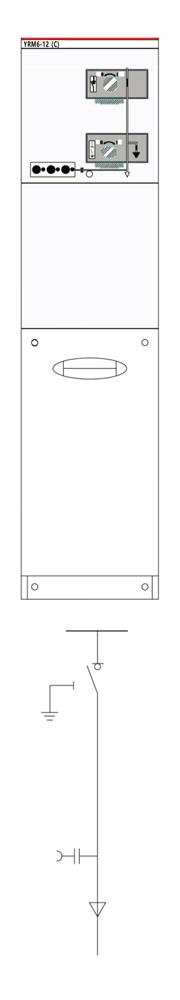
● D cabinet - lifting module
See standard configuration and features in "cable connection module without grounding knife" ● C cabinet - load switch module
See standard configuration and features in "load switch module"
● F cabinet-load switch and fuse combination module
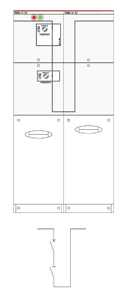
See standard configuration and characteristics in "load switch and fuse combination module" ● V cabinet - vacuum switch module
See standard configuration and features in "vacuum switch module"
● Capacitive voltage indicator for the incoming bushing
Install a pressure gauge that monitors SF6 density in each chamber
● Lifting lug
● Operating handle
Optional configurations
Electric operating mechanism/cable short circuit and ground fault indicator/current transformer and meter

Standard 2 circuits DF (260kg) Standard 2 circuits CCC (3000kg)
Optional configurations


Optional configurations


Standard expansion modules
| Model | Name | 12KV cabinet width | 24KV cabinet width |
| C | Load switch module | Width=325mm | Width=375mm |
| D | Cable connection module without grounding knife | Width=325mm | Width=375mm |
| F | Load switch fuse combination electrical module | Width=325mm | Width=375mm |
| V | Vacuum circuit breaker module | Width=325mm | Width=375mm |
| SL | Busbar segmentation switch module (load switch) | Width=325mm | Width=375mm |
| SVBR | Busbar segmentation switch module (vacuum circuit breaker) Sv is always with the bus lifting module | Width=650mm | Width=650mm |
| M | Meter module 12kV | Width=695mm | Width=695mm |
| PT | Module | Width=370 or 695mm | Width=370 or 695mm |
Note: A single module must add extension before it can be used.


Expansion module-load switch module C
Standard configuration and characteristics
● 630A internal bus
● Three working-position load/earth switch
● Three working-position single-spring operating mechanism, with two independent load switch and earth switch operating shafts
● Load switch and earth switch position indication
● Outgoing bushing in front horizontal arrangement, 630A 400 series bolted bushing
● Capacitive voltage indicator indicating that the bushing is live
● For all switch functions, there is a convenient add-on padlock on the panel
● SF6 gas pressure gauge (only one in each SF6 gas box)
● Ground busbar
● Interlocking of the earth switch to the front panel of the cable compartment
Optional configuration and characteristics
● Reserved bus extension
● External bus
● Load switch operation motor 110V/220V DC/AC
● Short circuit and ground fault indicator
● Measure toroidal current transformer and ammeter
● Meter toroidal current transformer and watt-hour meter
● A lightning arrester or double cable head can be installed at the cable incoming bushing
● Key interlocking1
● lncoming live grounding lock (lock the earth switch when the bushing is energized) 110V/220VAC
● Auxiliary contacts
Load switch position 2NO+2NC Earth switch position 2NO+2NC
Pressure gauge with signal 1 NO
Arc extinguisher with signal contact 1 NO ● Secondary device can be installed in
Secondary line chamber at the top of the switchgear Low voltage box at the top of the switchgear
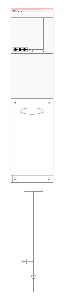
Expansion module-without grounding knife module D
Standard Configuration and Characteristics
● 630A internal bus
● Outgoing bushing in front horizontal arrangement, 630A 400 series bolted bushing
● Capacitive voltage indicator indicating that the bushing is live
● SF6 gas pressure gauge (only one in each SF6 gas box)
● Ground busbar
Optional configuration and characteristics
● Reserved bus extension
● External bus
● Short circuit and ground fault indicator
● Measure toroidal current transformer and ammeter
● Meter toroidal current transformer and watt-hour meter
● A lightning arrester or double cable head can be installed at the cable incoming bushing
● Secondary device can be installed in
Secondary line chamber at the top of the switchgear Low voltage box at the top of the switchgear
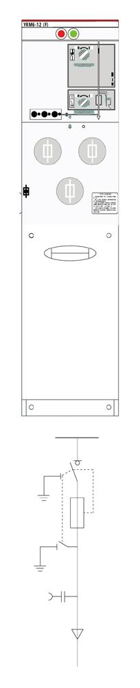
Expansion module-load switch and fuse combination module F
Standard Configuration and Characteristics
● 630A internal bus
● Three working-position load switch, the fuse head end is mechanically linked with the fuse tail end earth switch
● Three working-position double-spring operating mechanism, with two independent load switch and earth switch operating shafts
● Load switch and earth switch position indication
● Fuse tube
● Fuse placed horizontally
● Fuse tripping indication
● Outgoing bushing in front horizontal arrangement,200A 200 series plug-in bushing
● Capacitive voltage indicator indicating that the bushing is live
● For all switch functions, there is a convenient add-on padlock on the panel
● SF6 gas pressure gauge (only one in each SF6 gas box)
● Ground busbar
● Fuses for transformer protection parameter 12kV max.125A fuse
● Interlocking of the earth switch to the front panel of the cable compartment
Optional configuration and characteristics
● Reserved bus extension
● External bus
● Load switch operation motor 110/220V DC/AC
● Paralleling tripping coil 110/220V DC/AC
● Paralleling closing coil 110/220V DC/AC
● Measure toroidal current transformer and ammeter
● Meter toroidal current transformer and watt-hour meter
● Incoming live grounding lock (lock the earth switch when the bushing is energized) 110V/220V AC
● Auxiliary contacts
Load switch position 2NO+2NC Earth switch position 2NO+2NC Pressure gauge with signal 1 NO Fuse blown 1 NO
● Secondary device can be installed in
Secondary line chamber at the top of the switchgear Low voltage box at the top of the switchgear
Expansion module-busbar sectional switch module (circuit breaker) SVBR
Standard configuration and characteristics
● 630A internal bus
● 630A vacuum circuit breaker
● Two working-position double-spring operating mechanism for vacuum circuit breaker
● Vacuum circuit breaker lower disconnect switch
● Disconnect switch single-spring operating mechanism
● Mechanical interlocking of vacuum circuit breaker and disconnect switch
● Vacuum circuit breaker and disconnect switch position indication
● For all switch functions, there is a convenient add-on padlock on the panel
● SF6 gas pressure gauge (only one in each SF6 gas box)
● SV is always connected to the busbar lifting switchgear, occupying two module widths together
Optional configuration and characteristics
● Reserved bus extension
● External bus
● Vacuum circuit breaker operation motor 110V/220V DC/AC
● Paralleling tripping coil 110/220V DC/AC
● Paralleling closing coil 110/220V DC/AC
● Key interlocking
● Auxiliary contacts
Circuit breaker position 2NO+2NC
Disconnect switch position 2NO+2NC ● Secondary device can be installed in
Secondary line chamber at the top of the switchgear Low voltage box at the top of the switchgear
Expansion module - vacuum circuit breaker module V
Standard configuration and characteristics
● 630A internal bus
● 630A transformer/line protection vacuum circuit breaker
● Two working-position double-spring operating mechanism for vacuum circuit breaker
● Vacuum circuit breaker lower three working-position disconnect/earth switch
● Three working-position disconnectearth switch single-spring operating mechanism
● Mechanical interlocking of vacuum circuit breaker and three working-position switch
● Vacuum circuit breaker and three working-position switch position indication
● Electronic protection relay
● Trip coil (for relay action)
● Outgoing bushing in front horizontal arrangement, 630A 400 series bolted bushing
● Capacitive voltage indicator indicating that the bushing is live
● For all switch functions, there is a convenient add-on padlock on the panel
● SF6 gas pressure gauge (only one in each SF6 gas box)
● Ground busbar
● lnterlocking of the earth switch to the front panel of the cable compartment
Optional configuration and characteristics
● Reserved bus extension
● External bus
● Vacuum circuit breaker operation motor 110V/220V DC/AC
● Paralleling tripping coil 110/220V DC/AC
● Paralleling closing col 110/220V DC/AC
● Measure toroidal current transformer and ammeter
● Meter toroidal current transformer and watt-hour meter
● Incoming live grounding lock (lock the earth switch when the bushing is energized) 110V/220V AC
● Key interlocking
● Auxiliary contacts
Vacuum switch position 2NO+2NC
Disconnect switch position 2NO+2NC Earth switch position 2NO+2NC
Vacuum switch trip signal 1 NO Pressure gauge with signal 1 NO
● Secondary device can be installed in
Secondary line chamber at the top of the switchgear
Low voltage box at the top of the switchgear ● Other relays such as SPAJ140C
Expansion module-busbar sectional switch module (load switch)SL
Standard configuration and characteristics
● 630A internal bus
● Disconnect switch
● Single-spring operating mechanism
● Switch position indication
● For all switch functions, there is a convenient add-on padlock on the panel
● SF6 gas pressure gauge (only one in each SF6 gas box)
Optional configuration and characteristics
● Reserved bus extension
● External bus
● Load switch operation motor 110V/220V DC/AC
● Key interlocking
● Auxiliary contacts
Load switch position 2NO+2NC
● Secondary device can be installed in
Secondary line chamber at the top of the switchgear Low voltage box at the top of the switchgear
Expansion module-12kv voltage transformer cabinet
Standard configuration and characteristics
● 1pc or 2pcs voltage transformer
● Fuse for PT protection
● Voltmeter
W × H × D=695 × 1334 ×820mm
W × H × D=695 × 1680 ×820mm (with instrument box)
Optional configuration and characteristics
● Zinc oxide arrester (695 width)
● Capacitive voltage indicator indicating the switchgear is electrified
lncoming / outgoing line protection
● Use vacuum switch / vacuum circuit breaker module
● The transformer or line protection is a vacuum switch/vacuum circuit breaker, with protective relays and current transformers. When the fauilt curent reaches the setting current set by the protection relay, the protection relay issues acommand to trip the switch through the trip unit.)
Transformer / line protection
The YRM6 provides two types of transformer protection: load switch fuse combination and circuit breaker with relay protection.
Use load switch fuse combination module
Transformer protection is a combination of current limiting high voltage fuse and load switch. The fuse compartment will be mounted behind a separate, latched enclosure at the front of the unit. The load switch uses a spring charging mechanism that can be triggered by a fuse striker. To facilitate the replacement of the fuse, an operating handle can be used to remove the end cap of the fuse compartment. The trip mechanism of the fuse is placed in front to ensure the water proof performance of the entire system. The load switch fuse
combination uses a spring-loaded type of backup-protection type current limiting fuse, and the striker side faces the front of the switchgear during installation.
Fuse-transformer comparison table
| 100% | Rated capacity of power transfoormer (KVA) | |||||||||||||||
| Un(kV) | 25 | 50 | 75 | 100 | 125 | 160 | 200 | 250 | 315 | 400 | 500 | 630 | 800 | 1000 | 1250 | 1600 |
| 3 | 16 | 25 | 25 | 40 | 40 | 50 | 50 | 80 | 100 | 125 | 160 | 160 | ||||
| 3.3 | 16 | 25 | 25 | 40 | 40 | 50 | 50 | 63 | 80 | 100 | 125 | 160 | ||||
| 4.15 | 10 | 16 | 25 | 25 | 40 | 40 | 40 | 50 | 63 | 80 | 100 | 125 | 160 | |||
| 5 | 10 | 16 | 25 | 25 | 25 | 40 | 40 | 50 | 50 | 63 | 80 | 100 | 160 | 160 | ||
| 5.5 | 6 | 16 | 16 | 25 | 25 | 25 | 25 | 50 | 50 | 63 | 80 | 100 | 125 | 160 | ||
| 6 | 6 | 16 | 16 | 25 | 25 | 25 | 25 | 40 | 50 | 50 | 80 | 100 | 125 | 160 | 160 | |
| 6.6 | 6 | 16 | 16 | 25 | 25 | 25 | 25 | 40 | 50 | 50 | 63 | 80 | 100 | 125 | 160 | |
| 10 | 6 | 10 | 10 | 16 | 16 | 25 | 25 | 25 | 40 | 40 | 50 | 50 | 80 | 80 | 125 | 125 |
| 11 | 6 | 6 | 10 | 16 | 16 | 25 | 25 | 25 | 25 | 40 | 50 | 50 | 63 | 80 | 100 | 125 |
| 12 | 6 | 6 | 10 | 16 | 16 | 16 | 16 | 25 | 25 | 40 | 40 | 50 | 63 | 80 | 100 | 125 |
| 13.8 | 6 | 6 | 10 | 10 | 16 | 16 | 16 | 25 | 25 | 25 | 40 | 50 | 50 | 63 | 80 | 100 |
| 15 | 6 | 6 | 10 | 10 | 16 | 16 | 16 | 25 | 25 | 25 | 40 | 40 | 50 | 63 | 80 | 100 |
| 17.5 | 6 | 6 | 6 | 10 | 10 | 16 | 16 | 16 | 25 | 25 | 25 | 40 | 50 | 50 | 63 | 80 |
| 20 | 6 | 6 | 6 | 10 | 10 | 16 | 16 | 16 | 25 | 25 | 25 | 40 | 40 | 50 | 63 | 63 |
| 22 | 6 | 6 | 6 | 6 | 10 | 10 | 10 | 16 | 16 | 25 | 25 | 25 | 40 | 50 | 50 | 63 |
| 24 | 6 | 6 | 6 | 6 | 10 | 10 | 10 | 16 | 16 | 25 | 25 | 25 | 40 | 40 | 50 | 63 |
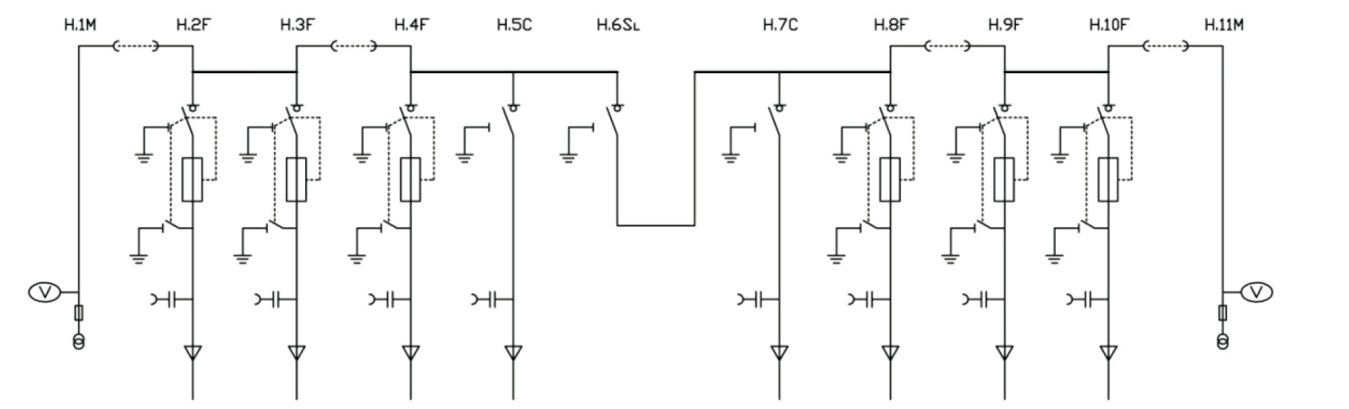
Plan lnstructions
Plan 1 CCF+
lncoming line installed lightning arrester and with reserved extension

Plan 2 CCFFF=CF
1 set at most 5 units, more than 5 units need to expand the bus connection

Plan 3 VV=M=FFF
High voltage side measurement

Plan 4 PT=FF=FCSLCF=FF=PT
PT Single busbar section with busbar PT

Annex
1. Auxiliary contacts
2NO+2 NC indicator switch positions are available on all load switches and circuit breakers. A parallel trip coil(AC or DC) can be mounted to the transformer/switch breaker. The LV control unit is located behind the front panel.
2. Voltage indication
A capacitive voltage indicator indicates whether the bushing is energized and the socket on it can be used for the nuclear phase.
3. Short circuit / ground fault indicator
To facilitate fault location, the cable switch module can be equipped with a short circuit/ground fault indicator for simple fault detection.
4. Electric operation
The manual operation of the cable switch unit and the transformer unit is a standard solution. lt is also possible to install an electric operating mechanism. Cable switch, vacuum circuit breaker, and earth switch are operated by mecharism located behind the front panel. All switches and circuit breakers can be operated by operating the handle (standard configuration) or can be equipped with a motor operating mechanism (accessory). However, the earth switch can only be operated manually and is equipped with a
mechanism that has the ability to close the fault current. Electric operating mechanisms are easy to implement in stages.
5. Cable connection
The YRM6 switchgear is fitted with standard bushings. All bushings are the same height from the ground and are protected
by a cable compartment cover. This cover can be interlocked with the earth switch. For dual cabincoming, a dedicated dual cable compartment cover can also be used.
6. Pressure indicator
Usually equipped with a pressure indicator, this indicator is in the form of a pressure gauge. Electrical contacts can also be provided to indicate a pressure drop.
7. External busbar
The YRM6 switchgear can be equipped with an external busbar with rated current 1250A.
8. Secondary line chamber / low voltage box
The YRM6 switchgear can be equipped with a secondary line compartment or a low voltage box at the top of the switchgear.
The secondary line compartment is used to install an ammeter (with or without a changeover switch)and a live blocking control unit. The low voltage box is used to install relays such as SPAJ140C,REF, and can also be equipped with an ammeter (with or without
changeover switch) and a live blocking control unit.
9.Lightning arrester
The cable incoming/outgoing module of the YRM6 type switchgear can be equipped with a zinc oxide lightning arrester at the cable; a zinc oxide lightning arrester can also be installed on the busbar or in the M cabinet.
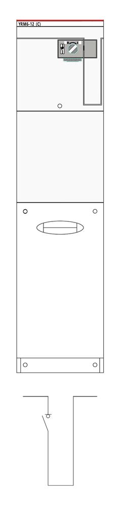
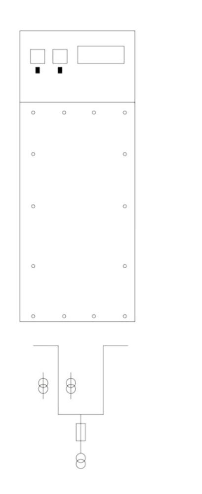
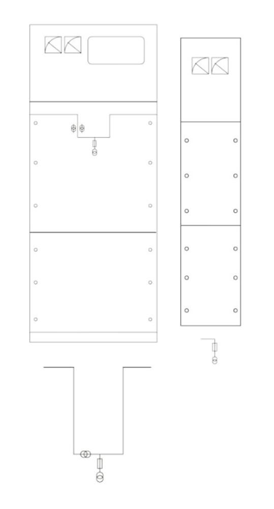
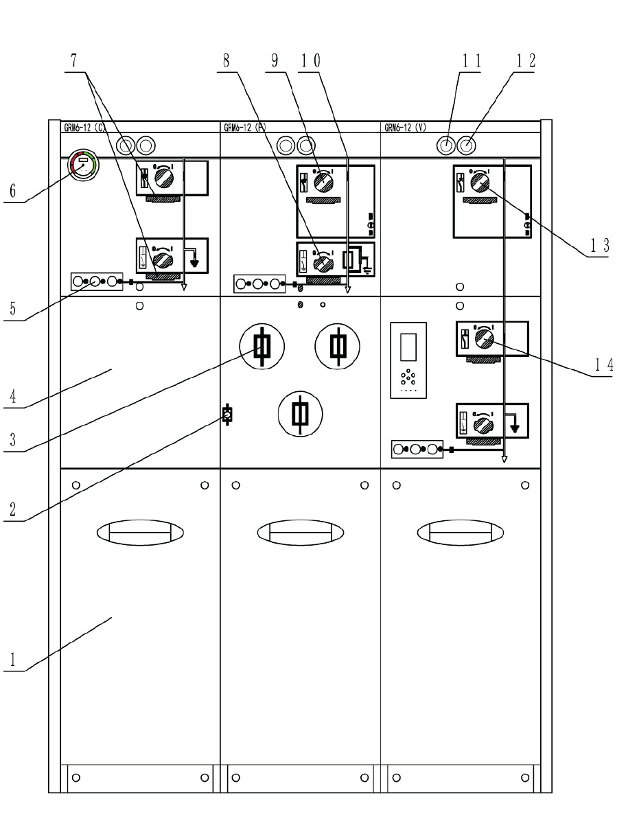
Switchgear structure diagram
1. Cable room
2. Fuse blow indicator
3. Fuse room
4. Installation room
5. charged display
6. Pressure indicator
7. Padlock device on the panel
8. Earth switch operating hole
9. Load switch operation hole
10. Analog circuit diagram
11. Opening button
12. Closing button
13. Circuit breaker operation hole
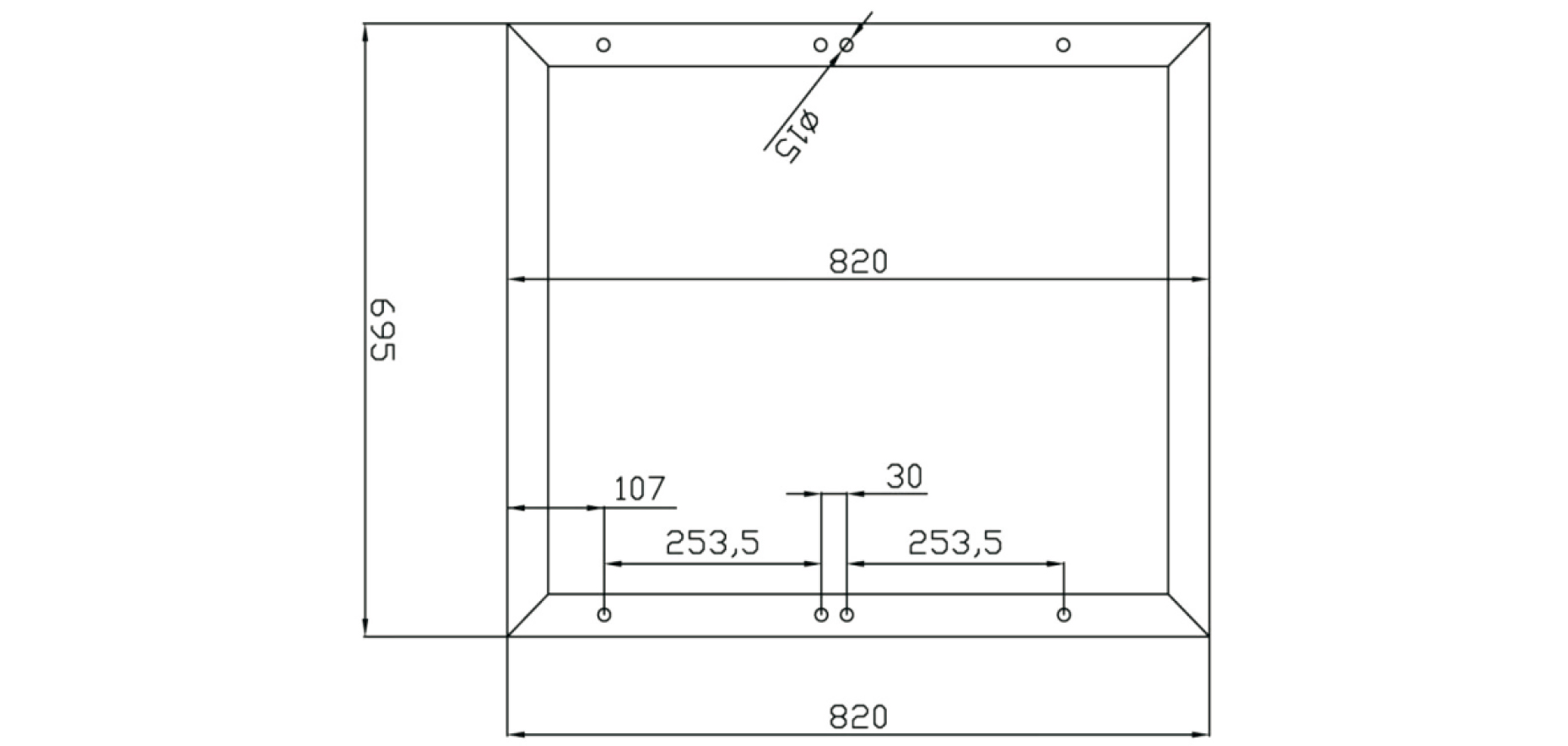
14. Disconnect switch operating hole foundation diagram
Overall and mounting dimensions(mm)
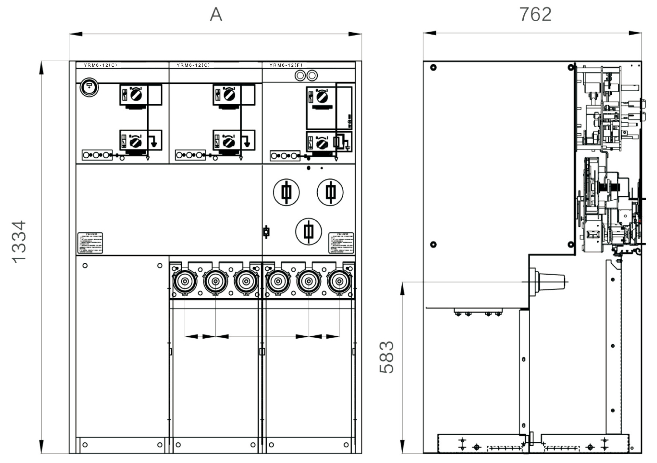
Foundation diagram
1. Standard unit
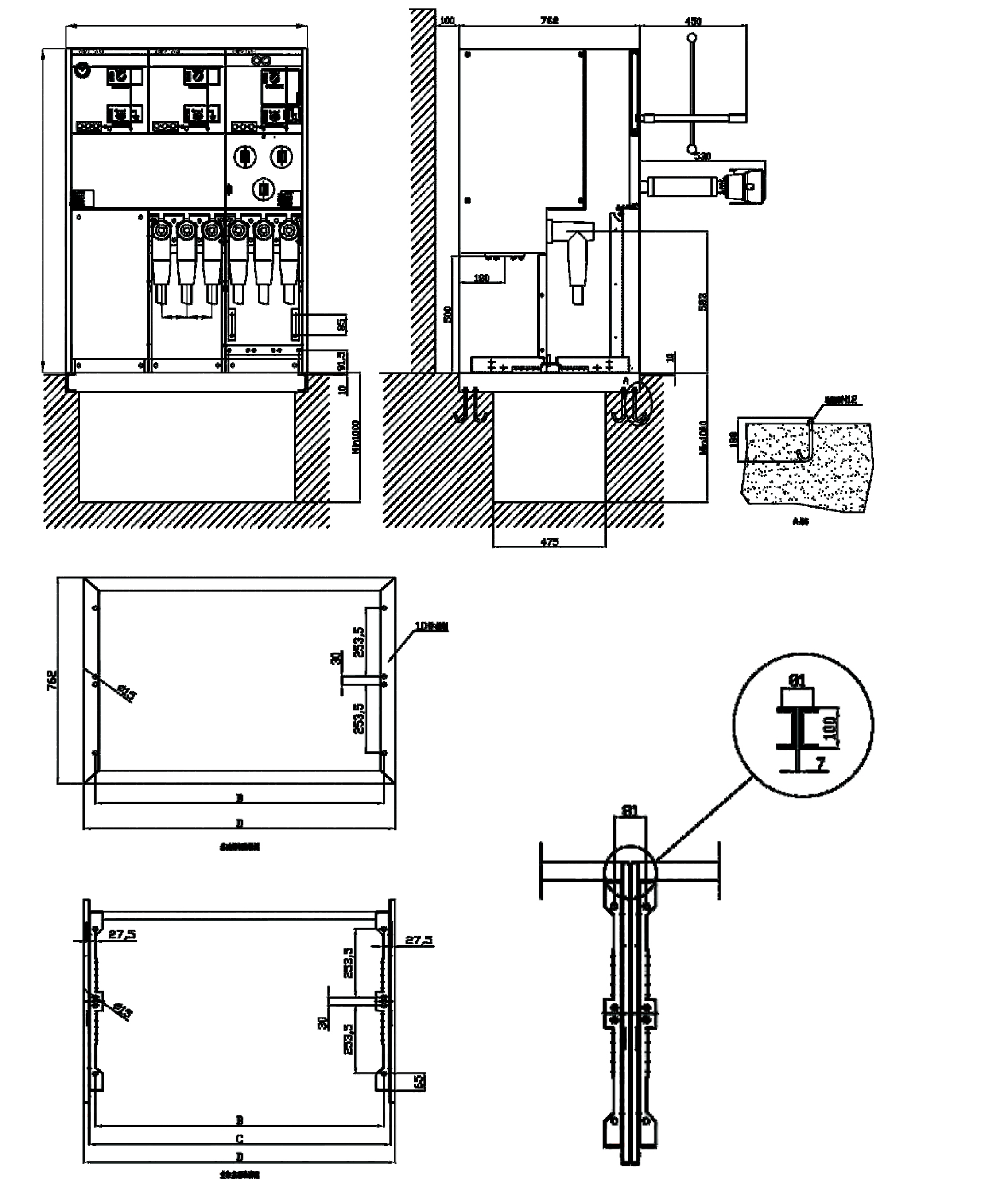
| Unit | A | B | C | D |
| 1-wqy | 370 | 297 | 336 | 370 |
| 2-wqy | 695 | 622 | 663 | 695 |
| 3-wqy | 1020 | 947 | 988 | 1020 |
| 4-wqy | 1345 | 1272 | 1313 | 1345 |
| 5-wqy | 1670 | 1597 | 1636 | 1670 |
Foundation diagram
2. 10kV metering cabinet
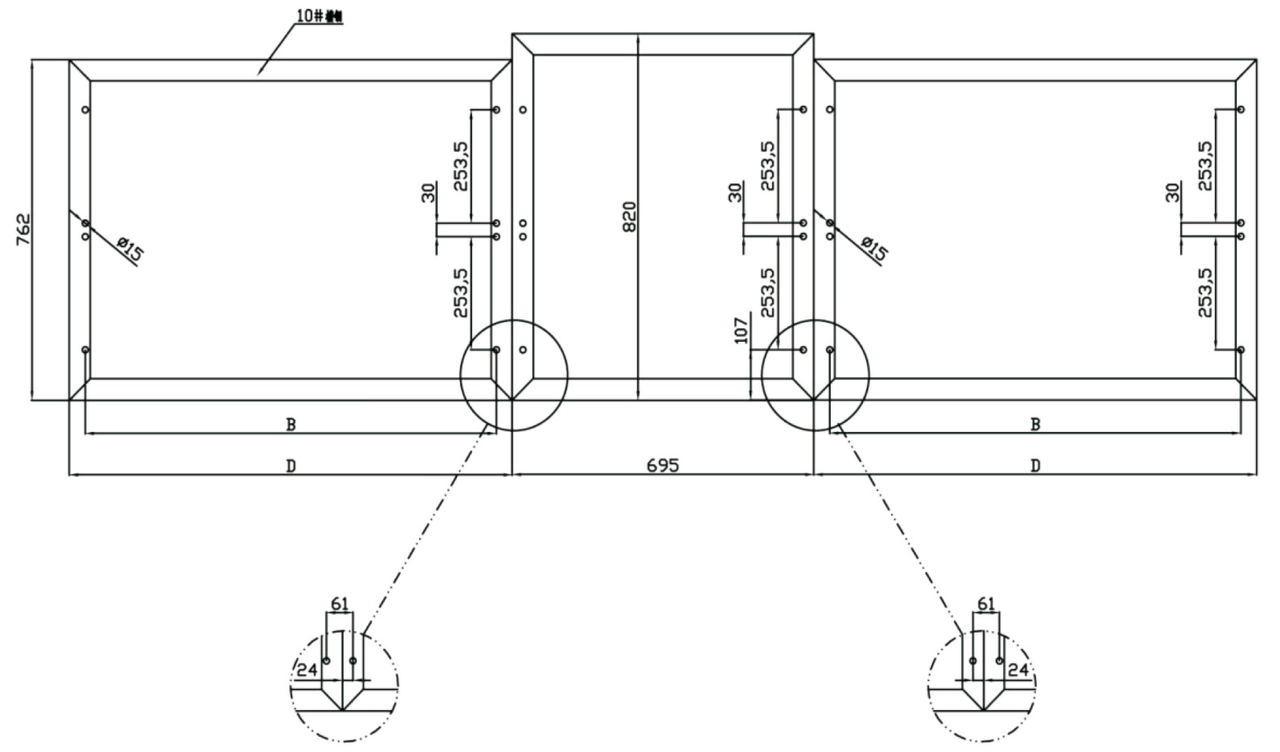
Top view of the base channel steel when the YRM6cabinet is connected to the 10kV M cabinet or PT cabinet
Foundation diagram of YRM6cabinet connected to 10kV M cabinet or PT cabinet
Ordering Instructions
When ordering, the following technical information must be provided:
● Main circuit diagram, arrangement diagram, and layout diagram
● Switchgear secondary circuit schematic diagram;
If the switchgear is used under special environmental conditions, it should be proposed.
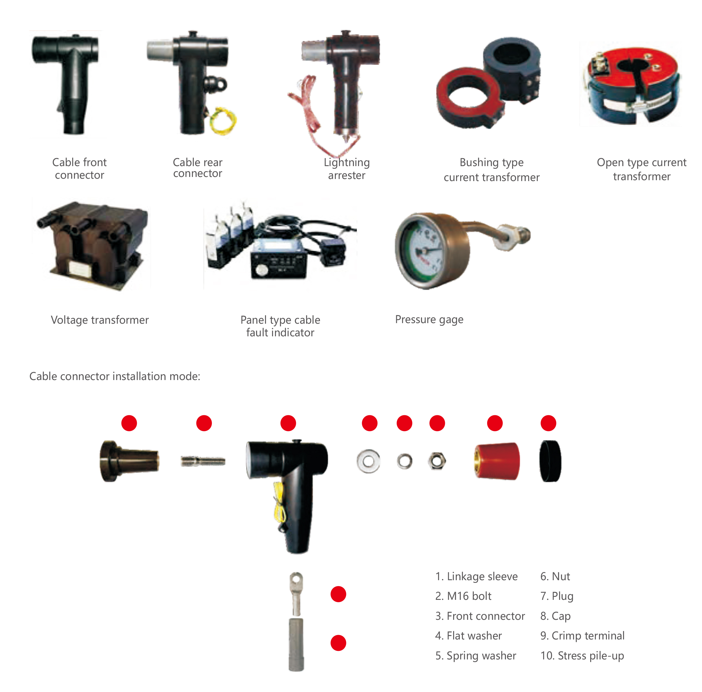
Accessories and auxiliary components
Cable accessories: used for connecting switchgear and external circuits, while ensuring the safety and reliability of electrical insulation. It mainly includes two types of front and rear cable joints, as shown in the following figure:
Leave Your Message


-

-

-

Address:CNC High-Tech Hutou Industrial Zone, Liushi Town, Yueqing, Wenzhou Ctity, China


Hot Products - Sitemap - AMP Mobile
3p Ac Mcb, 6a Elcb, 250amp Mccb Circuit Breaker, Mpcb, Mccb Microprocessor Based, 3 Phase Starter,