Projects
.jpg) Solutions
Solutions Services
 News
News About Us


Vector frequency inverter YCB600 Series
-
Product Overview
-
Product Details
-
Data Download
-
Related Products
.jpg "Vector frequency inverter YCB600 Series")
.jpg "Vector frequency inverter YCB600 Series")
.jpg "Vector frequency inverter YCB600 Series")
.jpg "Vector frequency inverter YCB600 Series")
.jpg "Vector frequency inverter YCB600 Series")
.jpg "Vector frequency inverter YCB600 Series")
.jpg "Vector frequency inverter YCB600 Series")
Vector frequency inverter YCB600 Series
An inverter is an electronic device used to control the speed of a motor. It achieves precise control of motor speed by changing the voltage and frequency that the motor receives.
Variable frequency drives are widely used in industrial applications for precise control of motor speeds, such as in fans, pumps, compressors, etc.
Contact Us
Product Details
General
An inverter is an electronic device used to control the speed of a motor. It achieves precise control of motor speed by changing the voltage and frequency that the motor receives.
Variable frequency drives are widely used in industrial applications for precise control of motor speeds, such as in fans, pumps, compressors, etc.
Operating conditions
1. Ambient temperature: -10°C~+45°C
2. Relative humidity: ≤20% at 40°C; ≤90% at 20°C
3. Altitude: ≤2000m
4. Environmental conditions: no harmful gases and vapors, no conductive or explosive dust, no severe mechanical vibration
Type designation
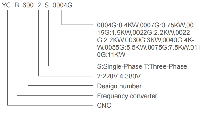
Technical data
| Inverter Model (A:Economy Type) |
Input Voltage(V) | Rated OutputCurrent (A) | Adaptive motorPower(kw) |
| YCB600-2S0004G | 220-240 | 2.4 | 0.4 |
| YCB600-2S0007G | 220-240 | 4.5 | 0.75 |
| YCB600-2S0015G | 220-240 | 7.0 | 1.5 |
| YCB600-2S0022G | 220-240 | 10.0 | 2.2 |
| YCB600-2S0030G | 220-240 | 11.0 | 3.0 |
| YCB600-4T0007G | 360-440 | 2.1 | 0.75 |
| YCB600-4T0015G | 360-440 | 3.7 | 1.5 |
| YCB600-4T0022G | 360-440 | 5.0 | 2.2 |
| YCB600-4T0030G | 360-440 | 7.0 | 3.0 |
| YCB600-4T0040G | 360-440 | 9.0 | 4.0 |
| YCB600-4T0055G | 360-440 | 13.0 | 5.5 |
| YCB600-4T0075G | 360-440 | 17.0 | 7.5 |
| YCB600-4T0110G | 360-440 | 25.0 | 11.0 |
Technical Indications
| ltem | ltem Description | |
| Input | Rated voltage &Frequency | Single-phase/3 Phase 200-240VAC,3 Phase 360-440VAC,50/60Hz |
| Allowable voltage working range | Voltage fluctuation range:±10%Voltage unbalance rate:<3%,Frequency fluctuation:≤5% |
|
| Ouput | Rated voltage Frequency | 3 Phase 0~Input voltage VAC |
| 0.0~600Hz | ||
| Overload capacity | 110%long-term,150%1 minute,180%5seconds | |
| Control your performance | Control mode | V/F control,Simplevector control,Advanced vector control Torque contro |
| Frequency resolution | Digital setting:0.1Hz Analog setting:Maximum frequency×0.1% |
|
| Frequency accuracy | Digital setting:0.1Hz Analog setting:within 0.2%of the maximum output frequency |
|
| V/FVoltage frequency characteristic | Three modes:the first is a linear torque characteristic curve,the second is a square torque characteristiccurve,and the third is a user-set V/F curve. |
|
| Automatic limit current and limit voltage |
No matter in the process of acceleration,deceleration or stable operation,it will automatically detect the motor stator current and voltage,and suppress it within the allowable range according to the unique algorithm,minimizing the possibilityof system fault tripping. |
|
| Vector voltage-frequency characteristics |
Automatically adjust output voltage-frequency ratio according to motor parameters and uniquealgorithm. |
|
| Torque characteristics | Starting torque: 100%rated torque at 5.0Hz(VF control) 150%rated torque at 1.0Hz(vectorcontrol) |
|
| Current and suppression | Full current closed-loop control,completely avoid current impact,with perfect overcurrent and overvoltage suppression function |
|
Technical Indications(continued)
| ltem | ltem Description | |
| Control your performance |
Under voltage suppression during operation |
Especially for users with low grid voltage and frequent grid voltage fluctuations,even if the voltage is lower than the allowable range,the system can maintain the longest possible running time according tothe unique algorithm and residual energy allocation strategy |
| Slip compensation | Setting range:0~100%,can automatically adjust the output frequency of the inverter according to the motor load,and reduce the rotation speed change of the motor caused by the load change |
|
| Carrier frequency | 2.0~20.0KHz | |
| Automatic voltageregulation operation |
Dynamic voltage stabilization,static voltage stabilization,and no voltage stabilization can be selected according to the need to obtain the most stable operation effect. |
|
| Built-in PID | It can easily constitute a closed-loop control system,suitable for process control such as pressure control and flow control |
|
| Running | Acceleration and deceleration time |
0.1~999.9s Continuous can be set |
| Running command | Operation panel control,external terminal control,serial communication control | |
| Frequency setting | Panel potentiometer setting,panel key setting,external control terminal increase/ decrease setting,analog voltage or current signal setting,terminal combination setting, serial communication setting,etc. |
|
| Output signal | One programmable relay output,one analogoutput | |
| Brake | Energy braking | Energy braking initial start voltage,return voltage andenergy braking rate are continuously adjustable |
| DC braking | Start and stop can be selected separately,action frequency 0.0~upper limit frequency, action current level 0~50%,action time 0~30s,continuous can be set |
|
| Other functions | Frequency upper and lower limit,reverse running limit,jog function,counter,skip frequency operation,instantaneous power failure restart,fault automatic reset,etc. |
|
| Protection function | Overcurrent,overload,overvoltage,undervoltage,overheating,short circuit,etc. | |
| LED Display | Can display the real-time of inverter running status,monitoring parameters,function parameters,fault codes and other information |
|
| Optional Parts | Brake components,remote operation panel and connecting cable | |
| Structure | Cooling method | Forced air cooling |
| Installation method | Wall-mounted,rail-mounted | |
Wiring diagram
Basic Wiring Diagram of Inverter
Basic Wiring Diagram
Dynamic voltage stabilization, static voltage stabilization, and no voltage stabilization can be selected according to the need to obtain the most stable operation effect.
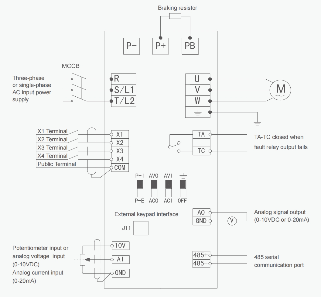
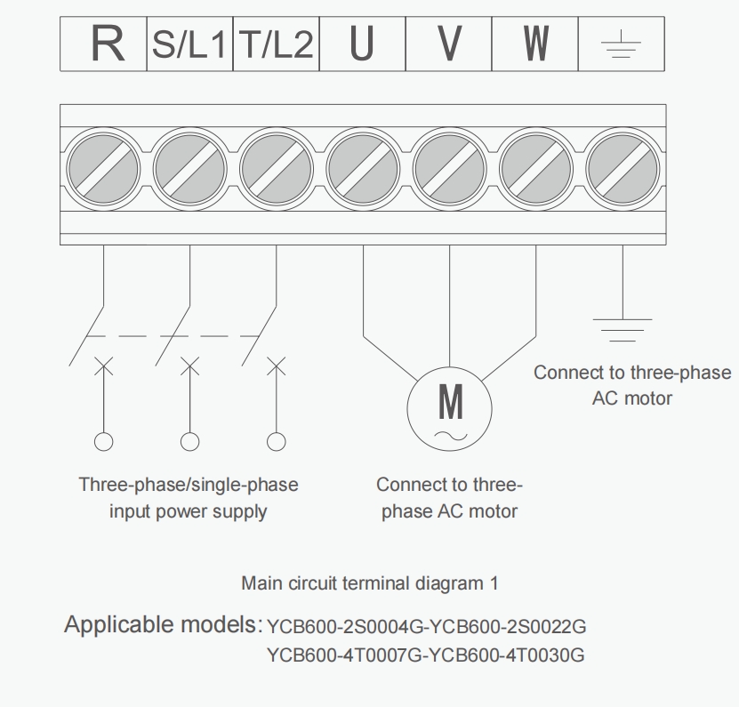
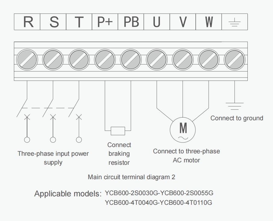
Main terminal
Control terminals
Control circuit terminals are shown in
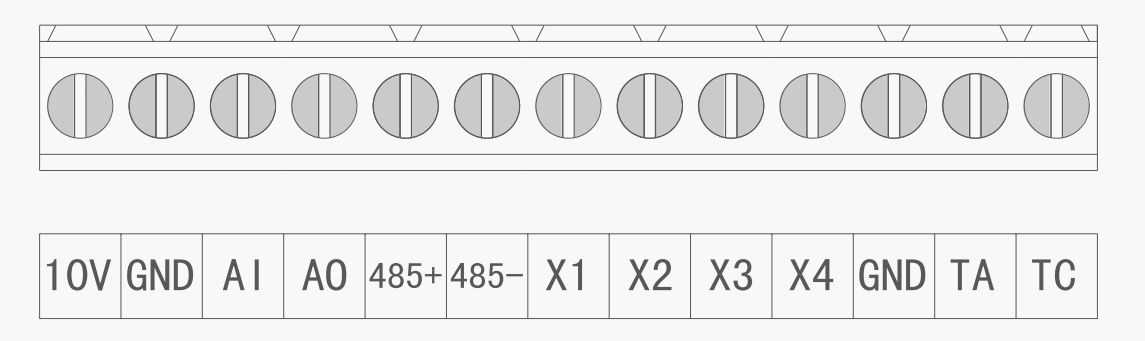
Control circuit terminals
Control circuit terminal
| Category | Terminal label | Function Description | Electrical Specifications |
| Analog power terminal | 10V | External analog given power supply, and GND,AL terminals connected to potentiometers,frequency setting can be performed |
OUTPUT,10V/10mA DC voltage |
| Public end | GND | Signal common terminal | |
| Analog input terminal | Al | Analog voltage signalinput,reference ground isGND |
INPUT,0~10V DCvoltage |
| Analog output terminal | AO | Programmable analog voltage output,the function is set by parameter F2.10,the reference ground is GND |
OUTPUT,0~10V DC voltage Or 0~20mA DC current |
| Communi cation terminal | 485+ | Positive end ofcommunication signal | |
| 485- | Communication signaln negative terminal |
Control circuit
| Category | Terminal label | Function Description | Electrical Specifications |
| Multi-funct ion inputterminal |
X1 | It is valid when Xn(n=1,2.3.4)-GNDis short-circuited,andits functions are respectively set by parameters F2.13~F2.16 |
INPUT,0~5V levelsignal, Active low,5mA |
| X2 | |||
| X3 | |||
| X4 | |||
| Programmable outputterminals |
TA | Relay contact output,Normal:TA-TC disconnected;When in action:TA-TC is closed;The function is set byparameterF2.20 |
Contact Rating:NO:240VAC-3A |
| TC | |||
| J1 | |||
| G | Indicates that the main control board is grounded | ||
| OFF | Indicates that the ground of the maincontrol board isdisconnected | ||
| J2 | |||
| AVO | Indicates analog AO output voltage signal,0-10V | ||
| ACO | Indicates analog AO output current signal,0-20mA
J4 |
||
| P-I
P-E |
Indicates that the built-in keyboard potentiometer is selected
Indicates the selection of an external keyboard potentiometer J5 |
||
| AVI | Indicates analog Al input voltage signal,0-10V | ||
| ACI | Indicates the analog Al input current signal,0-20mA | ||
Overall and mounting dimensions(mm)
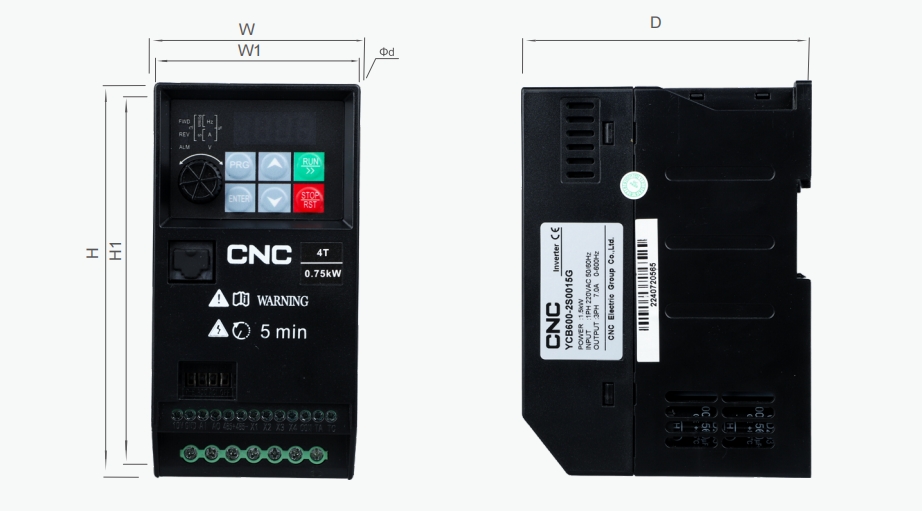
| inverter Model | Power(kg) | Dimension(MM) | |||||
| H | H1 | W | W1 | D | d | ||
| YCB600-2S0004G | 0.4 | 146 | 136.5 | 72 | 63 | 105 | φ4.5 |
| YCB600-2S0007G | 0.75 | ||||||
| YCB600-2S0015G | 1.5 | ||||||
| YCB600-2S0022G | 2.2 | ||||||
| YCB600-4T0007G | 0.75 | ||||||
| YCB600-4T0015G | 1.5 | ||||||
| YCB600-4T0022G | 2.2 | ||||||
| YCB600-4T0030G | 3.0 | ||||||
| YCB600-2S0030G | 3.0 | 182 | 172.5 | 87 | 78 | 127 | φ4.5 |
| YCB600-4T0040G | 4.0 | ||||||
| YCB600-4T0055G | 5.5 | ||||||
| YCB600-4T0040G | 4.0 | 240 | 229 | 118 | 106 | 155 | φ5.5 |
| YCB600-4T0055G | 5.5 | ||||||
| YCB600-4T0075G | 7.5 | ||||||
| YCB600-4T0110G | 11 | ||||||
Keypad Outline Dimension& Mounting holes Dimension
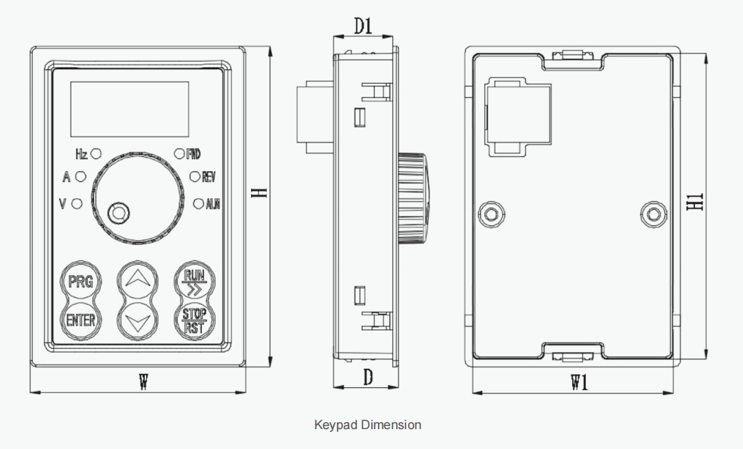
| Dimensions of keypad base holes | Keypad thickness | ||||
| W | W1 | H | H1 | D | D1 |
| 53mm | 49.4mm | 79mm | 75.4mm | 15.9mm | 14.5mm |
Tips:
• It needs to be equipped with an external display panel,WVhen the YCB600 series operation panel is led out.
• The opening size of the external display panel is:width 49.4mmx height 75.4mm.
Leave Your Message
Write your message here and send it to us

Related Products
-
 CJ40 AC ContactorCJ40(63-125) CJ40(160-250) CJ40(160-250) CJ40(630-1250) General Cj40 series AC contactor is mainly used for remote making & breaking circuits in power lines with AC 50Hz (or 60Hz), rated working voltage up to 690V (or 1140V), rated working current up to 1250A, and protect circuit from overload when assembling with thermal over-load relay or electronic protection device. Standard: I...
 -
 YCT8 Time RelayFunction Features -Single-function relay with possibility of time setting by a potentiometer. -Choice of 2 functions: A: Delay ON B: Delay OFF -Time scale 0.1 s -10 days divided into 10 ranges. -Relay status is indicated by LED. -1-MODULE.DIN rail mounting. Applications -Multifunction time relay can be used for electrical appliances, control of lights, heating, motors, pumps and fans (10 functions, 10 time ranges, multi-voltage). Function Features -10 functions: -...
 -
 CJX2s AC ContactorProduct Overview CJX2s series AC Contactor with novel appearance and compact structure is suitable for using starting & controlling the AC motor frequently, switching on and off the circuit at a long distance. It is used in combination with thermal relay to compose a magnetic motor starter. Standard: IEC 60947-1, IEC 60947-4-1. ...
 -
 60.12,60.13 General-purpose RelayContact Rating 2Z 3Z Contact Resistance 50mΩ(1A6VDC ) 50mΩ(1A6VDC ) Contact Capacity 10A/220VAC 10A/5A(NO/NC) 28VDC/220VAC 28VDC/220VAC Insulation Resistance 500MΩ, 500VDC Dielectric Strength BCC 1000VAC 1min BOC 1500VAC 1min Operating Time 30ms/20ms Terminal Type Socket ...
 -
 SSR-3 Solid State RelaySSR-3 032 38 □Z (Fundamental type) Item Data Load Voltage 380VAC,660VAC Load Current 10,15,20,25,30,40,50,60,75,80,100,120,150,200A Control Voltage 3-32VDC Control Current 20mA On Voltage ≤1.5V Off Leakage Current ≤10mA On-off Time ≤10mS Dielectric Strength 2500VAC Insulation Resistance 1000MΩ/500VDC Ambient Temperature -30~+75℃ Mounting Methods Bolted The work instructions LED ...
 -
 Motor protector YCP7General The YCP7 series AC motor starter is suitable for circuits with AC voltageup to 690V and current up to 32A. lt is used for overload, phase failure.short circuit protection, and infrequent starting control of three-phasesquirrel cage asynchronous motors. it can be used for distribution lineprotection and infrequent load switching, and can also be used as anisolator. Standards: IEC 60947-4-1,IEC 60947-4-2 Operating conditions 1. Ambient ...


Official shop


Follow us


-

-

-

Address:CNC High-Tech Hutou Industrial Zone, Liushi Town, Yueqing, Wenzhou Ctity, China


Copyright © 2025 CNC ELECTRIC GROUP CO.,LTD. All Rights Reserved.
Hot Products - Sitemap - AMP Mobile
3 Phase Starter, 6a Elcb, Mpcb, 250amp Mccb Circuit Breaker, Mccb Microprocessor Based, 3p Ac Mcb,
Hot Products - Sitemap - AMP Mobile
3 Phase Starter, 6a Elcb, Mpcb, 250amp Mccb Circuit Breaker, Mccb Microprocessor Based, 3p Ac Mcb,