 Projects
.jpg) Solutions
Solutions Services
 News
News About Us


-
Product Overview
-
Product Details
-
Data Download
-
Related Products

S□-M Series Dry-type Transformer
2. Short circuit protection
3. Controlling
4. Used in residential building, non-residential building, energy source industry and infrastructure.
5. According to the type of instantaneous release classified as follows : type B(3-5)ln, type C(5-10)ln, type D(10-20)ln
Contact Us
Product Details
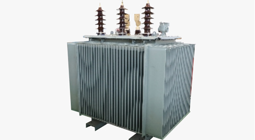
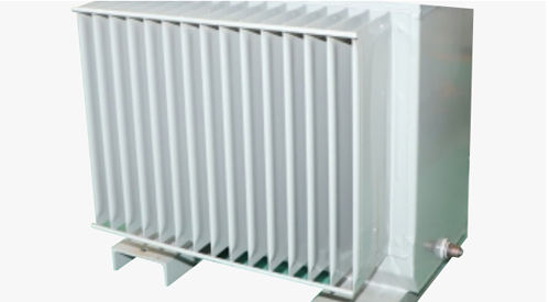
S □-M Series Oil-immersed Fully Sealed
The S□ -M series three-phase oil-immersed transformer adopts a fully oil-filled, sealed corrugated oil tank. and the oil tank shell adapts to the expansion performance of the oil with its own elasticity and meets the heat dissipation requirements. It has the characteristics of high efficiency and low loss, which
can save a lot of power consumption and operating costs, and is widely used in power plants, substations, industrial and mining enterprises, ports, airports and other environmental protection places.
Standard: IEC60076-1, IEC60076-2, IEC60076-3, IEC60076-5, IEC60076-10.
Selection

Operating conditions
1. Ambient temperature: maximum temperature: +40°C, minimum temperature: -25℃ .
2. Average temperature of the hottest month:+30℃, average temperature in the hottest year: +20℃ .
3. Altitude not exceeding 1000m.
4. The waveform of the power supply voltage is similar to a sine wave.
5. The three-phase supply voltage should be approximately symmetrical.
6. The total harmonic content of the load current shall not exceed 5% of the rated current.
7. Where to use: indoors or outdoors.
Features
1. The product has the characteristics of high efficiency, low loss, low noise, etc.
2. High mechanical strength, balanced ampere-turn distribution, and strong short-circuit resistance.
3. Low no-load and load loss.
4. Small size, reliable operation, long service life, and maintenance free.
Structure
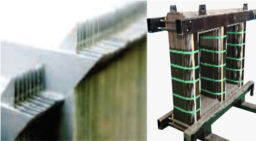
Iron core:
● The iron core is made of high-quality, high-performance, high-permeability silicon steel sheet,with low no-load loss.
High/low voltage winding:
● The low-voltage winding of 500KVA and below is a layer type, and the new spiral type is used for 630KVA and above.
● It has the characteristics of high mechanical strength, balanced ampere turn distribution, and strong short-circuit resistance.
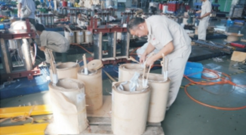
■ Fully sealed structure:
● The product is a fully sealed structure. The vacuum oil filling process is used for the transformer packaging, which completely removes the moisture of the transformer, ensures the isolation of the transformer oil from the outside air, prevents the aging of the oil, and improves the operation reliability of the transformer.
■ Positioning structure:
● The product body has added a positioning structure to prevent displacement during transportation, and all fasteners are equipped with fastening nuts to ensure that the fasteners do not loosen during long-term operation of the product.
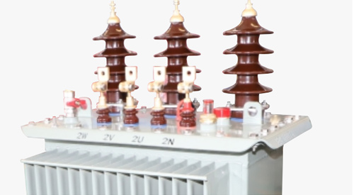
■ Oil tank:
● The oil tank adopts a corrugated oil tank.Simple process, high mechanical strength,good welding effect,not easy to leak,due to the strong fluidity of the oil, the heat dissipation capacity of the product is improved.
■ Other configuration:
● Equipped with pressure relief valve, signal thermometer, ensures the safe operation of the transformer.
S9-M 30~2500/10KV technical data
| Rated capacity (KVA) |
Voltage combination | Connection group label | No-load loss(W) | Load loss(W) | No-load current (%) |
Short circuit impedance (%) |
Dimensions | Total weight (kg) |
||||
| High voltage (KV) |
Tapping range |
Low voltage (KV) |
L | W | H | |||||||
| 30 | 6 6.3 10 10.5 11 |
±5 ±2 ×2.5 |
0.4 | Dyn11 Yyn0 Yzn11 |
130 | 630/600 | 2.3 | 4 | 745 | 530 | 890 | 280 |
| 50 | 170 | 910/870 | 2 | 790 | 560 | 940 | 365 | |||||
| 63 | 200 | 1090/1040 | 1.9 | 820 | 570 | 950 | 425 | |||||
| 80 | 250 | 1310/1250 | 1.9 | 850 | 580 | 1000 | 485 | |||||
| 100 | 290 | 1580/1500 | 1.8 | 900 | 620 | 1010 | 540 | |||||
| 125 | 340 | 1890/1800 | 1.7 | 880 | 630 | 1050 | 610 | |||||
| 160 | 400 | 2310/2200 | 1.6 | 950 | 690 | 1120 | 710 | |||||
| 200 | 480 | 2730/2600 | 1.5 | 990 | 730 | 1200 | 835 | |||||
| 250 | 560 | 3200/3050 | 1.4 | 1180 | 700 | 1200 | 970 | |||||
| 315 | 670 | 3830/3650 | 1.4 | 1230 | 760 | 1250 | 1125 | |||||
| 400 | 800 | 4520/4300 | 1.3 | 1260 | 800 | 1300 | 1310 | |||||
| 500 | 960 | 5410/5150 | 1.2 | 1400 | 900 | 1320 | 1530 | |||||
| 630 | Dyn11 Yyn0 Yzn11 |
1200 | 6200 | 1.1 | 4.5 | 1530 | 940 | 1350 | 1890 | |||
| 800 | 1400 | 7500 | 1 | 1580 | 1000 | 1420 | 2185 | |||||
| 1000 | 1700 | 10300 | 1 | 1770 | 1180 | 1450 | 2480 | |||||
| 1250 | 1950 | 12000 | 0.9 | 1920 | 1290 | 1430 | 3020 | |||||
| 1600 | 2400 | 14500 | 0.8 | 1990 | 1340 | 1620 | 3550 | |||||
| 2000 | 3000 | 17100 | 0.7 | 5 | 1950 | 1680 | 2100 | 4530 | ||||
| 2500 | 3300 | 23200 | 0.7 | 2020 | 1710 | 2100 | 5030 | |||||
Note 1:for transformers with rated capacity of 500kVA and below, the load loss values above the diagonal line in the table are applicable to the Dyn11 or Yzn11 coupling group,and the load loss values below the diagonal line are applicable to the Yyn0 coupling group.
Note 2:when the average annual load rate of the transformer is between 35% and 40%, the maximum operating eficiency can be obtained by using the loss value in the table.
Overall and mounting dimensions(mm)

Note:The dimensions and weights provided are only for reference in design and selection.The final size and weight are subject to our product drawings.
S11-M 30~2500 /10KV technical data
| Rated capacity (KVA) |
Voltage combination | Connection group label | No-load loss(W) | Load loss(W) | No-load current (%) |
Short circuit impedance (%) |
Dimensions | Total weight (kg) |
||||
| High voltage (KV) |
Tapping range |
Low voltage (KV) |
L | W | H | |||||||
| 30 | 6 6.3 10 10.5 11 |
±5 ±2 ×2.5 |
0.4 | Dyn11 Yyn0 Yzn11 |
100 | 630/600 | 1.5 | 4 | 690 | 510 | 920 | 275 |
| 50 | 130 | 910/870 | 1.3 | 730 | 510 | 960 | 340 | |||||
| 63 | 150 | 1090/1040 | 1.2 | 750 | 550 | 1000 | 385 | |||||
| 80 | 180 | 1310/1250 | 1.2 | 790 | 620 | 1020 | 450 | |||||
| 100 | 200 | 1580/1500 | 1.1 | 790 | 700 | 1040 | 520 | |||||
| 125 | 240 | 1890/1800 | 1.1 | 840 | 800 | 1070 | 625 | |||||
| 160 | 280 | 2310/2200 | 1 | 1070 | 670 | 1130 | 695 | |||||
| 200 | 340 | 2730/2600 | 1 | 1140 | 750 | 1140 | 795 | |||||
| 250 | 400 | 3200/3050 | 0.9 | 1200 | 800 | 1190 | 955 | |||||
| 315 | 480 | 3830/3650 | 0.9 | 1300 | 860 | 1210 | 1085 | |||||
| 400 | 570 | 4520/4300 | 0.8 | 1380 | 900 | 1240 | 1290 | |||||
| 500 | 680 | 5410/5100 | 0.8 | 1450 | 950 | 1300 | 1590 | |||||
| 630 | Dyn11 Yyn0 Yzn11 |
810 | 6200 | 0.6 | 4.5 | 1500 | 970 | 1360 | 1850 | |||
| 800 | 980 | 7500 | 0.6 | 1660 | 1140 | 1400 | 2210 | |||||
| 1000 | 1150 | 10300 | 0.6 | 1690 | 1190 | 1530 | 2570 | |||||
| 1250 | 1360 | 12000 | 0.5 | 1760 | 1230 | 1600 | 3115 | |||||
| 1600 | 1640 | 14500 | 0.5 | 1800 | 1250 | 1660 | 3520 | |||||
| 2000 | 1940 | 18300 | 0.4 | 5 | 1930 | 1360 | 1490 | 4060 | ||||
| 2500 | 2290 | 21200 | 0.4 | 2080 | 1360 | 1570 | 5105 | |||||
Note 1:for transformers with rated capacity of 500kVA and below, the load loss values above the diagonal line in the table are applicable to the Dyn11 or Yzn11 coupling group,and the load loss values below the diagonal line are applicable to the Yyn0 coupling group.
Note 2:when the average annual load rate of the transformer is between 35% and 40%, the maximum operating eficiency can be obtained by using the loss value in the table.
Overall and mounting dimensions(mm)

Note:The dimensions and weights provided are only for reference in design and selection.The final size and weight are subject to our product drawings.
S13-M 30~2500 /10KV technical data
| Rated capacity (KVA) |
Voltage combination | Connection group label | No-load loss(W) | Load loss(W) | No-load current (%) |
Short circuit impedance (%) |
Dimensions | Total weight (kg) |
||||
| High voltage (KV) |
Tapping range |
Low voltage (KV) |
L | W | H | |||||||
| 30 | 6 6.3 10 10.5 11 |
±5 ±2 ×2.5 |
0.4 | Dyn11 Yyn0 Yzn11 |
80 | 630/600 | 1.5 | 4 | 685 | 490 | 860 | 260 |
| 50 | 100 | 910/870 | 1.3 | 725 | 520 | 955 | 365 | |||||
| 63 | 110 | 1090/1040 | 1.2 | 750 | 535 | 970 | 415 | |||||
| 80 | 130 | 1310/1250 | 1.2 | 770 | 565 | 985 | 465 | |||||
| 100 | 150 | 1580/1500 | 1.2 | 800 | 595 | 1000 | 545 | |||||
| 125 | 170 | 1890/1800 | 1.1 | 815 | 670 | 1010 | 585 | |||||
| 160 | 200 | 2310/2200 | 1.1 | 1015 | 645 | 1055 | 695 | |||||
| 200 | 240 | 2730/2600 | 1 | 1020 | 650 | 1115 | 810 | |||||
| 250 | 290 | 3200/3050 | 1 | 1140 | 730 | 1120 | 930 | |||||
| 315 | 340 | 3830/3650 | 0.9 | 1195 | 785 | 1175 | 1075 | |||||
| 400 | 410 | 4520/4300 | 0.9 | 1265 | 855 | 1195 | 1255 | |||||
| 500 | 480 | 5410/5100 | 0.8 | 1325 | 915 | 1240 | 1435 | |||||
| 630 | Dyn11 Yyn0 Yzn11 |
570 | 6200 | 0.8 | 4.5 | 1465 | 960 | 1295 | 1880 | |||
| 800 | 700 | 7500 | 0.6 | 1515 | 995 | 1340 | 2145 | |||||
| 1000 | 830 | 10300 | 0.6 | 1605 | 1095 | 1460 | 2455 | |||||
| 1250 | 970 | 12000 | 0.5 | 1685 | 1145 | 1485 | 2840 | |||||
| 1600 | 1170 | 14500 | 0.5 | 1775 | 1225 | 1580 | 3310 | |||||
| 2000 | 1550 | 18300 | 0.4 | 5 | 1855 | 1265 | 1600 | 3960 | ||||
| 2500 | 1830 | 21200 | 0.4 | 1885 | 1305 | 1780 | 4980 | |||||
Note 1:for transformers with rated capacity of 500kVA and below, the load loss values above the diagonal line in the table are applicable to the Dyn11 or Yzn11 coupling group,and the load loss values below the diagonal line are applicable to the Yyn0 coupling group.
Note 2:when the average annual load rate of the transformer is between 35% and 40%, the maximum operating eficiency can be obtained by using the loss value in the table.
Overall and mounting dimensions(mm)

Note:The dimensions and weights provided are only for reference in design and selection.The final size and weight are subject to our product drawings.
S14-M 30~2500 /10KV technical data
| Rated capacity (KVA) |
Voltage combination | Connection group label | No-load loss(W) | Load loss(W) | No-load current (%) |
Short circuit impedance (%) |
Dimensions | Total weight (kg) |
||||
| High voltage (KV) |
Tapping range |
Low voltage (KV) |
L | W | H | |||||||
| 30 | 6 6.3 10 10.5 11 |
±5 ±2 ×2.5 |
0.4 | Dyn11 Yyn0 Yzn11 |
80 | 505/480 | 1.5 | 4 | 785 | 710 | 880 | 370 |
| 50 | 100 | 730/695 | 1.3 | 800 | 730 | 940 | 480 | |||||
| 63 | 110 | 870/830 | 1.2 | 815 | 720 | 970 | 535 | |||||
| 80 | 130 | 1050/1000 | 1.2 | 830 | 740 | 990 | 580 | |||||
| 100 | 150 | 1260/1200 | 1.1 | 875 | 790 | 1010 | 705 | |||||
| 125 | 170 | 1510/1440 | 1.1 | 875 | 770 | 1050 | 775 | |||||
| 160 | 200 | 1850/1760 | 1 | 935 | 820 | 1140 | 975 | |||||
| 200 | 240 | 2180/2080 | 1 | 995 | 870 | 1140 | 1140 | |||||
| 250 | 290 | 2560/2440 | 0.9 | 995 | 900 | 1180 | 1240 | |||||
| 315 | 340 | 3060/2920 | 0.9 | 1030 | 880 | 1250 | 1425 | |||||
| 400 | 410 | 3610/3440 | 0.8 | 1075 | 910 | 1270 | 1635 | |||||
| 500 | 480 | 4330/4120 | 0.8 | 1120 | 930 | 1320 | 1950 | |||||
| 630 | Dyn11 Yyn0 Yzn11 |
570 | 4960 | 0.6 | 4.5 | 1165 | 950 | 1350 | 2150 | |||
| 800 | 700 | 6000 | 0.6 | 1210 | 1050 | 1390 | 2515 | |||||
| 1000 | 830 | 8240 | 0.6 | 1520 | 1020 | 1450 | 2635 | |||||
| 1250 | 970 | 9600 | 0.5 | 1630 | 1090 | 1540 | 3210 | |||||
| 1600 | 1170 | 11600 | 0.5 | 1680 | 1150 | 1600 | 3905 | |||||
| 2000 | 1550 | 14600 | 0.4 | 5 | 1890 | 1300 | 1600 | 4130 | ||||
| 2500 | 1830 | 16900 | 0.4 | 1990 | 1360 | 1700 | 5250 | |||||
Note 1:for transformers with rated capacity of 500kVA and below, the load loss values above the diagonal line in the table are applicable to the Dyn11 or Yzn11 coupling group,and the load loss values below the diagonal line are applicable to the Yyn0 coupling group.
Note 2:when the average annual load rate of the transformer is between 35% and 40%, the maximum operating eficiency can be obtained by using the loss value in the table.
Overall and mounting dimensions(mm)

Note:The dimensions and weights provided are only for reference in design and selection.The final size and weight are subject to our product drawings.
S20-30~2500/10KV technical data
| Rated capacity (KVA) |
Voltage combination | Connection group label | No-load loss(W) | Load loss(W) | No-load current (%) |
Short circuit impedance (%) |
Dimensions | Total weight (kg) |
||||
| High voltage (KV) |
Tapping range |
Low voltage (KV) |
L | W | H | |||||||
| 30 | 6 6.3 10 10.5 11 |
±5 ±2 ×2.5 |
0.4 | Dyn11 Yyn0 Dyn5 |
70 | 505 | 1.2 | 4 | 785 | 710 | 880 | / |
| 50 | 90 | 730 | 1.04 | 800 | 730 | 940 | / | |||||
| 80 | 115 | 1050 | 0.96 | 830 | 740 | 990 | / | |||||
| 100 | 135 | 1265 | 0.88 | 875 | 790 | 1010 | / | |||||
| 125 | 150 | 1510 | 0.88 | 875 | 770 | 1050 | / | |||||
| 160 | 180 | 1850 | 0.8 | 935 | 820 | 1140 | / | |||||
| 200 | 215 | 2185 | 0.8 | 995 | 870 | 1140 | / | |||||
| 250 | 260 | 2560 | 0.72 | 995 | 900 | 1180 | / | |||||
| 315 | 305 | 3065 | 0.72 | 1030 | 880 | 1250 | / | |||||
| 400 | 370 | 3615 | 0.64 | 1075 | 910 | 1270 | / | |||||
| 500 | 430 | 4330 | 0.64 | 1120 | 930 | 1320 | / | |||||
| 630 | 510 | 4960 | 0.48 | 4.5 | 1165 | 950 | 1350 | / | ||||
| 800 | 630 | 6000 | 0.48 | 1210 | 1050 | 1390 | / | |||||
| 1000 | 745 | 8240 | 0.48 | 1520 | 1020 | 1450 | / | |||||
| 1250 | 870 | 9600 | 0.4 | 1630 | 1090 | 1540 | / | |||||
| 1600 | 1050 | 11600 | 0.4 | 1680 | 1150 | 1600 | / | |||||
| 2000 | 1225 | 14640 | 0.32 | 5 | 1890 | 1300 | 1600 | / | ||||
| 2500 | 1440 | 14840 | 0.32 | 1990 | 1360 | 1700 | / | |||||
Note 1:for transformers with rated capacity of 500kVA and below, the load loss values above the diagonal line in the table are applicable to the Dyn11 or Yzn11 coupling group,and the load loss values below the diagonal line are applicable to the Yyn0 coupling group.
Note 2:when the average annual load rate of the transformer is between 35% and 40%, the maximum operating eficiency can be obtained by using the loss value in the table.
Overall and mounting dimensions(mm)

Note:The dimensions and weights provided are only for reference in design and selection.The final size and weight are subject to our product drawings
S22-30~2500/10KV technical data
| Rated capacity (KVA) |
Voltage combination | Connection group label | No-load loss(W) | Load loss(W) | No-load current (%) |
Short circuit impedance (%) |
Dimensions | Total weight (kg) |
||||
| High voltage (KV) |
Tapping range |
Low voltage (KV) |
L | W | H | |||||||
| 30 | 6 6.3 10 10.5 11 |
±5 ±2 ×2.5 |
0.4 | Dyn11 Yyn0 Dyn5 |
65 | 455 | 1.2 | 4 | 785 | 710 | 880 | / |
| 50 | 80 | 655 | 1.04 | 800 | 730 | 940 | / | |||||
| 80 | 105 | 945 | 0.96 | 830 | 740 | 990 | / | |||||
| 100 | 120 | 1140 | 0.88 | 875 | 790 | 1010 | / | |||||
| 125 | 135 | 1360 | 0.88 | 875 | 770 | 1050 | / | |||||
| 160 | 160 | 1665 | 0.8 | 935 | 820 | 1140 | / | |||||
| 200 | 190 | 1970 | 0.8 | 995 | 870 | 1140 | / | |||||
| 250 | 230 | 2300 | 0.72 | 995 | 900 | 1180 | / | |||||
| 315 | 270 | 2760 | 0.72 | 1030 | 880 | 1250 | / | |||||
| 400 | 330 | 3250 | 0.64 | 1075 | 910 | 1270 | / | |||||
| 500 | 385 | 3900 | 0.64 | 1120 | 930 | 1320 | / | |||||
| 630 | 460 | 4460 | 0.48 | 4.5 | 1165 | 950 | 1350 | / | ||||
| 800 | 560 | 5400 | 0.48 | 1210 | 1050 | 1390 | / | |||||
| 1000 | 665 | 7415 | 0.48 | 1520 | 1020 | 1450 | / | |||||
| 1250 | 780 | 8640 | 0.4 | 1630 | 1090 | 1540 | / | |||||
| 1600 | 940 | 10440 | 0.4 | 1680 | 1150 | 1600 | / | |||||
| 2000 | 1085 | 13180 | 0.32 | 5 | 1890 | 1300 | 1600 | / | ||||
| 2500 | 1280 | 13360 | 0.32 | 1990 | 1360 | 1700 | / | |||||
Note 1:for transformers with rated capacity of 500kVA and below, the load loss values above the diagonal line in the table are applicable to the Dyn11 or Yzn11 coupling group,and the load loss values below the diagonal line are applicable to the Yyn0 coupling group.
Note 2:when the average annual load rate of the transformer is between 35% and 40%, the maximum operating eficiency can be obtained by using the loss value in the table.
Overall and mounting dimensions(mm)

Note:The dimensions and weights provided are only for reference in design and selection.The final size and weight are subject to our product drawings.
S-30~2500/20KV technical data
| Rated capacity (KVA) |
Voltage combination | Connection group label | No-load loss(W) | Load loss(W) | No-load current (%) |
Short circuit impedance (%) |
Dimensions | Total weight (kg) |
||||
| High voltage (KV) |
Tapping range |
Low voltage (KV) |
L | W | H | |||||||
| 25 | 20 10 6 |
±5 ±2 ×2.5 |
0.4 | Dyn11 Yyn0 Dyn5 |
63 | 600 | 1.7 | 5.5(20kV) 4 (6kV, 10kV) |
1090 | 600 | 1150 | / |
| 50 | 81 | 750 | 1.6 | 1120 | 620 | 1180 | / | |||||
| 100 | 130 | 1250 | 1.3 | 1150 | 650 | 1290 | / | |||||
| 160 | 189 | 1750 | 1.1 | 1160 | 675 | 1380 | / | |||||
| 250 | 270 | 2350 | 0.96 | 1200 | 880 | 1400 | / | |||||
| 315 | 324 | 2800 | 0.88 | 1230 | 920 | 1460 | / | |||||
| 400 | 387 | 3250 | 0.8 | 1250 | 950 | 1580 | / | |||||
| 500 | 459 | 3900 | 0.8 | 1390 | 960 | 1580 | / | |||||
| 630 | 540 | 4600 | 0.72 | 6(20kV) 4.5 (6kV, 10kV) |
1450 | 980 | 1600 | / | ||||
| 800 | 585 | 6000 | 0.64 | 1560 | 1020 | 1720 | / | |||||
| 1000 | 693 | 7600 | 0.56 | 1700 | 1070 | 1790 | / | |||||
| 1250 | 855 | 9500 | 0.56 | 1700 | 1070 | 1791 | / | |||||
| 1600 | 1080 | 12000 | 0.48 | 1850 | 1130 | 1850 | / | |||||
| 2000 | 1305 | 15000 | 0.48 | 6(20kV) 5 (6kV, 10kV) |
2000 | 1280 | 1980 | / | ||||
| 2500 | 1575 | 18500 | 0.4 | 2040 | 1320 | 2050 | / | |||||
| 3150 | 1980 | 23000 | 0.4 | 2200 | 1400 | 2250 | / | |||||
Note 1:for transformers with rated capacity of 500kVA and below, the load loss values above the diagonal line in the table are applicable to the Dyn11 or Yzn11 coupling group,and the load loss values below the diagonal line are applicable to the Yyn0 coupling group.
Note 2:when the average annual load rate of the transformer is between 35% and 40%, the maximum operating eficiency can be obtained by using the loss value in the table.
Overall and mounting dimensions(mm)

Note:The dimensions and weights provided are only for reference in design and selection.The final size and weight are subject to our product drawings.
Related Products
-
 SZ□-35KV Oil-Immersed Transformer.SZ□-35KV Series On-load Voltage Regulating Transformer This kind of product is applied to power system of three-phase, 50Hz as well as 35kV and below,is the main transformer equipment of medium and small-sized transformer substation, supplies power distribution, power and illumination for the industry and agriculture. The company introduces in domestic and overseas advanced technique, adopts the latest material and optimizes design, which enables the product structur...
 -
10 Dry-type Transformer") SG(B)10 Dry-type TransformerSG(B)10 Insulated Three-phase Dry-type Transformer The non-encapsulated coil three-phase dry type power transformer that adopt UL certificated NOMEX insulation system, with advantages of safe, reliable, energy saving, fireproof, explosion resistant, simple maintaining and so on. It has superior design, reasonable structure, elegant appearance, and its main performance index is superior to domestic standard, such as local discharge level, no-load loss, load loss,noise...
SG(B)10 Dry-type TransformerSG(B)10 Insulated Three-phase Dry-type Transformer The non-encapsulated coil three-phase dry type power transformer that adopt UL certificated NOMEX insulation system, with advantages of safe, reliable, energy saving, fireproof, explosion resistant, simple maintaining and so on. It has superior design, reasonable structure, elegant appearance, and its main performance index is superior to domestic standard, such as local discharge level, no-load loss, load loss,noise... -
 S□-35KV Series Oil-Immersed Transformer.S□-35KV Series Non-excitation Voltage Regulating Transformer This kind of product is applied to power system of three-phase, 50Hz as well as 35kV and below,is the main transformer equipment of medium and small-sized transformer substation, supplies power distribution, power and illumination for the industry and agriculture. The company introduces in domestic and overseas advanced technique, adopts the latest material and optimizes design, which enables the product st...
 -
 SCB9 Dry-type TransformerThe SC (B) series epoxy resin dry type transformers have the advantages of flame retardant, fireproof, explosion-proof, maintenance free, and small size due to their coils being encapsulated with epoxy resin. They can be directly installed in load centers and are widely used in power transmission and transformation systems, as important places as commercial residences, public buildings, airports, as well as in harsh environments like subways, smelt...
 -
 S□-ML SeriesS口-ML Series Three-dimensional Wound Core Oil-immersed Transformer S □ -ML series three-dimensional wound core oil immersed transformer produced by the company is a new generation transiom product with more reasonable structure, lower operation noise, better performance and stronger reliabilty. The product breaks through the traditional plane structure and adopts three-phase symmetrical three-dimensional structure. The three cores are arranged in an equilateral tria...
 -
 KS9 Oil-Immersed Transformer.KS9 Three-phase Mining Oil-immersed Transformer KS9 series oil immersed mining transformer is suitable for central transformer substation, mining stop, general wind dypass and main wind dypass which has gas but has not explosive ganger. Moreover, it is suitable for the moisture environment. The iron cores of these series transformers adopt silicon steel slice, which is made of excellent low loss crystal granule. They have the advantages such as low no-load loss, smal...


-

-

-

Address:CNC High-Tech Hutou Industrial Zone, Liushi Town, Yueqing, Wenzhou Ctity, China


Hot Products - Sitemap - AMP Mobile
Mccb Microprocessor Based, 3 Phase Starter, 250amp Mccb Circuit Breaker, 3p Ac Mcb, 6a Elcb, Mpcb,