Projects
.jpg) Solutions
Solutions Services
 News
News About Us


Motor protector YCP7
-
Product Overview
-
Product Details
-
Data Download
-
Related Products
Motor protector YCP7
Picture


Motor protector YCP7
The YCP7 series AC motor starter is suitable for circuits with AC voltageup to 690V and current up to 32A. lt is used for overload, phase failure.short circuit protection, and infrequent starting control of three-phasesquirrel cage asynchronous motors. it can be used for distribution lineprotection and infrequent load switching, and can also be used as anisolator.
Standards: IEC 60947-4-1,IEC 60947-4-2
Contact Us
Product Details
General
The YCP7 series AC motor starter is suitable for circuits with AC voltageup to 690V and current up to 32A. lt is used for overload, phase failure.short circuit protection, and infrequent starting control of three-phasesquirrel cage asynchronous motors. it can be used for distribution lineprotection and infrequent load switching, and can also be used as anisolator.
Standards: IEC 60947-4-1,IEC 60947-4-2
Operating conditions
1. Ambient temperature: -5°C~+40°C
2. Relative humidity: ≤20% at 40°C; ≤90% at 20°C
3. Altitude: ≤2000m
4. The inclination between the starter and the vertical installation surface shall not exceed ±5
5. Environmental conditions: no harmful gases and vapors, no conductive or explosive dust,no severe mechanical vibration
Type designation
| Company code |
Protector | Current shell frame |
Method of operation |
Current | ||||
| YC | P7 | - | 32 | B | 0.1-0.16A | |||
| MotorCircuit Breaker |
protector | 32A | Slide left and right |
0.1-0.16 0.16-0.25 0.25-0.4 0.4-0.63 0.63-1 1-1.6 1.6-2.5 2.5-4 |
4-6.3 6-10 9-14 13-18 17-23 20-25 24-32 |
|||
Technical data
| Rated insulation voltage Ui(V) | 690 |
| Rated impulse withstand voltage Uimp(V) | 8000 |
| Rated working voltage Ue(V) | AC230/240,AC400/415,AC440,AC500,AC690 |
| Rated frequency (Hz) | 50/60 |
| usage categories | A,AC-3 |
| The shell protection level | IP20 (front side). |
| Product number | Rated current of release In(A) |
Setting current Adjustment range(A) |
Rated ultimate short-circuit breaking capacity Icu,rated operating short-circuit breaking capacity lcs kA |
Flying arc distance (mm) |
|||
| AC 400/415V | AC 690V | ||||||
| Icu | Ics | Icu | Ics | ||||
| YCP7-32B | 0.16 | 0.1~0.16 | 100 | 100 | 100 | 100 | 40 |
| 0.25 | 0.16-0.25 | 100 | 100 | 100 | 100 | 40 | |
| 0.4 | 0.25-0.4 | 100 | 100 | 100 | 100 | 40 | |
| 0.63 | 0.4-0.63 | 100 | 100 | 100 | 100 | 40 | |
| 1 | 0.63-1 | 100 | 100 | 100 | 100 | 40 | |
| 1.6 | 1-1.6 | 100 | 100 | 100 | 100 | 40 | |
| 2.5 | 1.6-2.5 | 100 | 100 | 4 | 4 | 40 | |
| 4 | 2.5-4 | 100 | 100 | 4 | 4 | 40 | |
| 6.3 | 4-6.3 | 100 | 100 | 4 | 4 | 40 | |
| 10 | 6-10 | 100 | 100 | 4 | 4 | 40 | |
| 14 | 9-14 | 25 | 15 | 4 | 4 | 40 | |
| 18 | 13-18 | 25 | 15 | 4 | 4 | 40 | |
| 23 | 17-23 | 25 | 15 | 4 | 4 | 40 | |
| 25 | 20-25 | 25 | 15 | 4 | 4 | 40 | |
| 32 | 24-32 | 25 | 15 | 4 | 4 | 40 | |
Rated power of three-phase motor controlled by starter
| Product number | Rated current of release In(A) |
Setting current Adjustment range(A) |
Standard rated powe ofthree-phase motor (kW) | |||||
| AC-3,50Hz/60Hz | ||||||||
| 230/240V | 400V | 415V | 440V | 500V | 690V | |||
| YCP7-32B | 0.16 | 0.1~0.16 | - | - | - | - | - | - |
| 0.25 | 0.16-0.25 | - | - | - | - | - | - | |
| 0.4 | 0.25-0.4 | - | - | - | - | - | - | |
| 0.63 | 0.4-0.63 | - | - | - | - | - | 0.37 | |
| 1 | 0.63-1 | - | - | - | 0.37 | 0.37 | 0.55 | |
| 1.6 | 1-1.6 | - | 0.37 | - | 0.55 | 0.75 | 1.1 | |
| 2.5 | 1.6-2.5 | 0.37 | 0.75 | 0.75 | 1.1 | 1.1 | 1.5 | |
| 4 | 2.5-4 | 0.75 | 1.5 | 1.5 | 1.5 | 2.2 | 3 | |
| 6.3 | 4-6.3 | 1.1 | 2.2 | 2.2 | 3 | 3.7 | 4 | |
| 10 | 6-10 | 2.2 | 4 | 4 | 4 | 5.5 | 7.5 | |
| 14 | 9-14 | 3.4 | 5.5 | 5.5 | 7.5 | 7.5 | 9 | |
| 18 | 13-18 | 5.5 | 7.5 | 9 | 9 | 9 | 11 | |
| 23 | 17-23 | 5.5 | 11 | 11 | 11 | 11 | 15 | |
| 25 | 20-25 | 15 | 11 | 11 | 11 | 15 | 18.5 | |
| 32 | 24-32 | 7.5 | 15 | 15 | 15 | 18.5 | 25 | |
Note: When using a starter in a line with the presence of high-order harmonics (such as frequency converters and other equipment), the specifispecifications of the starter should be selected according to the actual situation, which is 1.3 to 1.9 times the rated current of the motor, Forexamplewhen the rated current of the motor is 1.1A, for lines without high-order hamonics, the starter specifications should be selected: 1-1.6A;for circuitswith high-order harmonics, it is recommended to choose a starter specification of 1.6-2.5A.
Overcurrent protection characteristics
| Serial Number | Setting current multiple | Initial state | Set time | Expected results | ambientair temperature |
| 1 | 1.05 | cold state | t≥2h | Non release | +20℃±2C |
| 2 | 1.2 | Hot state (rising tothe specified current immediately afterthe first test) |
t<2h | trip | +20C±2°C |
| 3 | 1.5 | Starting after thermal balance of 1 times the set current |
t<2min | trip | +20C±2°C |
| 4 | 7.2 | cold state | 2s<t≤10s | trip | +20C±2C |
Note:The operating characteristics of the starter during load balancing of each phase
| Serial Number | Setting current multiple | Initial state | Set time | Expected results |
ambient air temperature |
|
| Any two phases | The third phase | |||||
| 1 | 1 | 0.9 | cold state | t≥2h | Non release | +20°C±2℃ |
| 2 | 1.15 | 0 | Hot state (rising to the specified current immediately after the first test) |
t<2h | trip | +20°C±2℃ |
Note:Action characteristics of the starter when the load of each phase is unbalanced(phase failure)
| Serial Number | Setting current multiple | Initial state | Set time | Expected results | ambient air temperature |
| 1 | 1 | cold state | t≥2h | Non release | +40°C±2℃ |
| 2 | 1.2 | Hot state (rising to the specified cur- rent immediately after the first test) |
t<2h | trip | +40°C±2℃ |
| 3 | 1.5 | Hot state (after reaching equilibrium at 1.0 times the set current) |
t<2min | trip | +40°C±2°C |
| 4 | 1.05 | cold state | t≥2h | Non release | -5°℃±2℃ |
| 5 | 1.3 | Hot state (rising to the specified curent immediately after the third test) |
t<2h | trip | -5°C±2°℃ |
| 6 | 1.5 | Hot state (after reaching equilibrium at 1.0 times the set current) |
t<4min | trip | -5°C±2°℃ |
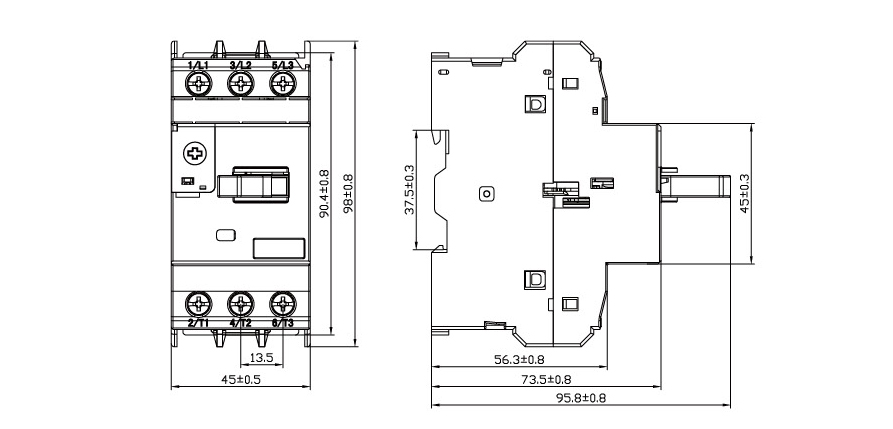
Overall and mounting dimensions(mm)
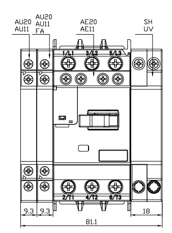
| Accessory name | YCP7-32B |
| Undervoitage release | YCP7-UV110 |
| YCP7-UV220 | |
| YCP7-UV380 | |
| Shunt release | YCP7-SH110 |
| YCP7-SH220 | |
| YCP7-SH380 | |
| Instantaneous auxiliary contact(front | YCP7-AE20 |
| hanging) | YCP7-AE11 |
| Instantaneous auxiliary contact(side mounted)Fault signal contact andin- stantaneous auxiliary contact |
YCP7-AU20 |
| YCP7-AU11 | |
| YCP7-AD0110
YCP7-AD1010 |
|
| YCP7-AD0101 |

YCP7-UV
| Rated insulation voltage Ui(V) | 690 |
| Rated impulse withstand voltage Uimp (kV): |
6 |
| Action characteristics: | When the voltage drops to within the range of 70%and 35%of the rated voltage,the undervoltage release should act,Undervoltage release in power supplyWhen the voltage is lower than 35%of the rated voltage of the release,the undervotage release shoulkd be able to prevent the starter from closing;The power supplyvoltage is equal to or greater than At 85%of the rated voltage of the release,the undervoltage release should ensure that the starter is closed |
Auxiliary accessories

YCP7-SH
| Rated insulation voltage Ui (V) | 690 |
| Rated impulse withstand voltage Uimp(kV): |
6 |
| Action characteristics: | Action characteristics:The operating voltage range of the shunt release is 70%to 110%of the rated working voltage. |

YCP7-AE
| Rated insulation voltage Ui(V) | 250 | |||||||
| Rated impulse withstand voltage Uimp(kV) | 2.5 | |||||||
| Agreed heating current Ith (A) | 2.5 | |||||||
| Usage category | AC-15 | DC-13 | ||||||
| Rated working voltage Ue(V) | 24 | 48 | 110/127 | 230/240 | 24 | 48 | 60 | |
| Rated working current IE(A) | 2 | 1.25 | 1 | 0.5 | 1 | 0.3 | 0.15 | |
| Normal working power P(W) | 48 | 60 | 127 | 120 | 24 | 15 | 9 | |

YCP7-AU
| Rated insulation voltage Ui(V): | 690 |
| Rated impulse withstand voltage Uimp(kV): | 4 |
| Agreed heating current Ith (A): | 6 |
| Usage category | AC-15 | DC-13 | ||||||||||
| Rated working voltage Ue(V) | 48 | 110/127 | 230/240 | 380/415 | 440 | 500 | 690 | 24 | 48 | 60 | 110 | 220 |
| Rated working current IE(A) | 6 | 4.5 | 3.3 | 2.2 | 1.5 | 1 | 0.6 | 6 | 5 | 3 | 1.3 | 0.5 |
| Normal working power P(W) | 300 | 500 | 720 | 850 | 650 | 500 | 400 | 140 | 240 | 180 | 140 | 120 |

YCP7-FA
| Rated insulation voltage Ui(V) | 690 |
| The aqreed heatingcurrent Ith (A)of the instan- taneous auxiliary contact |
6 |
| The agreed heating current Ith(A)of the fault signal contact |
2.5 |
| Rated impulse withstand voltage Uimp (kV)of fault siqnal contact |
2.5 |
| Rated impulse withstand voltage Uimp (kV)of instantaneous auxiliary contacts |
4 |
| Usage category | AC-14 | DC-13 | |||||
| Rated working voltage Ue (V) | 24 | 48 | 110/127 | 230/240 | 24 | 48 | 60 |
| Rated working current IE (A) | 2 | 1 | 0.5 | 0.3 | 1 | 0.3 | 0.15 |
| Normal working power P (W) | 48 | 48 | 72 | 72 | 24 | 15 | 9 |
| Operational performance (times) | 1000 | 1000 | 1000 | 1000 | 1000 | 1000 | 1000 |
| Usage category | Connect | Disconnection | Number of switching operation cycles and operation frequency | ||||||
| Vle | u/ue | Cosφor T0.95 | I/le | u/ue | Cosφor T0.95 | Numberof oper- ation cycles |
Number of operationcycles perminute | Power on time | |
| AC-14 | 6 | 1.1 | 0.7 | 6 | 1.1 | 0.7 | 10 | 2 | 0.05 |
| AC-15 | 10 | 1.1 | 0.3 | 10 | 1.1 | 0.3 | 10 | 2 | 0.05 |
| DC-13 | 1.1 | 1.1 | 6Pe | 1.1 | 1.1 | 6Pe | 10 | 2 | 0.05 |
Ordering Notice
When placina an order, specify the product model, specifications, and auantity.
For example, ordering 50 AC motor starters with a current regulation range of 9-14A for YCP7-32B is written as: YCP7-32B/9-14A 50 units
For example, ordering 10 units of 110V 50Hz undervoltage release is written as YCP7-UV110 10 units
For example, ordering 10 instantaneous auxiliary contact groups with a heating current of 6A, including one normaly open contact and onenormally closed contact,is written as YCP7-AU11, 10 units
Leave Your Message
Write your message here and send it to us

Related Products
-
 LW28,YCD12 Sealed Type Power Cut off Switch16A-20A 25A-32A Technical data Model specification Dimensions(mm) Mounting dimensions(mm) P N M C A1 A2 YCD12-16A 100 80 65 35 60 90 YCD12-20A 100 80 65 35 60 90 YCD12-25A 125 100 85 35 60 115 YCD12-32A 125 100 85 35 60 115 YCD12-40A 175 114 100 35 60 165 YCD12-63A 175 114 100 35 60 165 YCD12-100A 240 160 120 45 ...
 -
 TZ Micro SwitchCharacteristics / Application Contact Form External Appearance Size TZ-6000 TZ-6001 TZ-6101 TZ-6103 TZ-6002 TZ-6102 ...
 -
 YCP6 Motor Protector
 -
 CJX2s-M AC ContactorResponsive 3D Model .sketchfab-embed-wrapper { position: relative; padding-bottom: 56.25%; /* 16:9 ratio */ height: 0; overflow: hidden; max-width: 100%; background: #000; } .sketchfab-embed-wrapper iframe { position: absolute; top: 0; left: 0; width: 100%; height: 100%; border: ...
 -
 JD-8 Motor Integrated ProtectorOperating conditions The altitude shall not exceed 2000m. The ambient air temperature is -5℃~+40℃ and the average temperature within 24h shall not exceed +35℃. Atmospheric condition: Relative humidity of atmosphere shall not exceed 50% at the temperature of +40℃,and higher relative humidity is allowed at lower temperature. For example, the air humidity can reach 90% at the temperature of +20℃. Regarding the condensation casually caused by humidity change, special me...
 -
 TB17 TimersTB17 Item No. Data Voltage AC 110~240V DC 12~24V 50/60Hz Contact Timed SPDTc Operation Time operation Timing range 24H TB35 Item No. Data Voltage AC 110~240V DC 12~24V 50/60Hz Contact Timed SPDTc Timing range 24H


Official shop


Follow us


-

-

-

Address:CNC High-Tech Hutou Industrial Zone, Liushi Town, Yueqing, Wenzhou Ctity, China


Copyright © 2025 CNC ELECTRIC GROUP CO.,LTD. All Rights Reserved.
Hot Products - Sitemap - AMP Mobile
Mpcb, 250amp Mccb Circuit Breaker, 3 Phase Starter, 3p Ac Mcb, 6a Elcb, Mccb Microprocessor Based,
Hot Products - Sitemap - AMP Mobile
Mpcb, 250amp Mccb Circuit Breaker, 3 Phase Starter, 3p Ac Mcb, 6a Elcb, Mccb Microprocessor Based,